


 Chinese
 Spanish
 Russian
 Portuguese
 French
 German
 Indonesian
 Thai
 Vietnamese
 Arabic
 Italian
 Turkish
 Polish
 Japanese



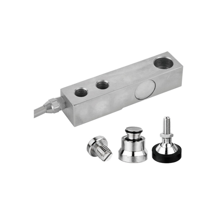
METRAVON MV-LC0150 is a single-ended shear beam load cell for platform scales, pallet scales and weighing assemblies. Two mounting holes secure one end; force enters through the loading connection at the other. Capacity options run from 250 kg to 10 t, but the body dimensions and loading thread change between capacity groups.
Shear beam load cell dimensions by capacity
The loading foot or connector must transmit force at the intended point without allowing the platform to contact the sensing beam elsewhere. A higher-capacity version is not necessarily a drop-in replacement: the fixing-hole spacing, overall length and loading thread can all change.
| Rated capacities | Overall length L | Fixing-hole spacing L2 | Loading thread M |
|---|---|---|---|
| 0.25/0.5/1/1.5/2/2.5 t | 133.4 mm | 25.4 mm | M12 × 1.75 |
| 3, 5, 7.5 t | 171.5 mm | 38.1 mm | M20 × 2.5 |
| 10 t | 222.2 mm | 50.8 mm | M24 × 2 |
Use the full capacity-specific drawing to check the fixing-hole diameters, clearances and installed height. The table is not a machining drawing. A load foot, mounting plate or complete weigh module should be specified as a separate part of the assembly, not assumed to be included with the bare sensor.
Capacity is a per-sensor limit
Include the platform's own weight and the heaviest expected load on one support. Dividing the total load by four is insufficient when a pallet can be placed near a corner or dropped onto one side. Zeroing the empty platform removes its displayed weight, not the mechanical load carried by the cells.
The specified safe overload is 150% FS. It is not an additional operating range or a substitute for checking impact and stop clearances. If the application includes frequent shock loading, provide the loading sequence and restraint design for assessment before ordering.
Bridge connection and configuration
| Electrical item | Value |
|---|---|
| Rated output | 2.0 ± 0.002 mV/V |
| Recommended excitation | 4-12 VDC; maximum 15 VDC |
| Input resistance | 385 ± 10 ohms |
| Output resistance | 351 ± 2 ohms |
| Connection | Four-wire bridge with shield |
For a multi-cell scale, confirm the indicator's excitation capacity for the complete bridge network and the junction box's trimming arrangement. A suitable junction box and signal cable help connect the cells; neither turns the raw bridge output into a PLC current signal.
Specify alloy steel or stainless steel, required enclosure protection, cable length and actual operating temperature in the enquiry. Environmental and cable details must appear on the selected configuration's datasheet; a general model name does not identify every option.
Platform-scale installation questions
Q1. Can I replace only one cell in a four-cell platform?
Only after checking the existing cells' capacity, rated output, bridge resistance and mechanical interfaces. A matching nominal capacity alone is not enough. After replacement, repeat corner loading and span calibration because the platform's load distribution and electrical balance may have changed.
Q2. Does a longer cable require a different calibration?
A four-wire installation is affected by resistance in the excitation leads. Agree the final cable length and routing before calibration, and document any extension. Recheck the scale after changing a cable rather than assuming that the previous span setting remains valid.
Q3. Which checks are needed before the platform enters service?
Verify clearance from the frame and overload stops, stable empty-platform zero, response at each corner and repeated loading at agreed test points. Investigate a corner-dependent error mechanically before adjusting electrical trim. Record the completed assembly and indicator settings with the acceptance results.
Q4. What information makes the quotation specific?
Provide the platform size, dead weight, maximum gross load, cell count, load placement and proposed foot or connector. Add the existing indicator model and installation drawing for replacements. State any approval requirement explicitly so that the applicable documentation can be checked before purchase.
Send the platform layout for an MV-LC0150 quotation, including the capacity group and mounting accessories required.
