


 Chinese
 Spanish
 Russian
 Portuguese
 French
 German
 Indonesian
 Thai
 Vietnamese
 Arabic
 Italian
 Turkish
 Polish
 Japanese



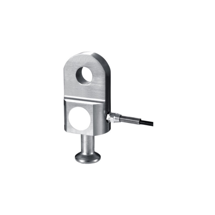
METRAVON MV-LC0131 is a transmission-line load cell documented for installation between an insulator string and crossarm in online ice-load monitoring systems. The reference versions are 7, 12, 16, 25, 30, 32, 42 and 55 t. It supplies a mechanical load signal; interpreting that signal as conductor icing requires the line geometry and a defined monitoring method.
Match the transmission-line load cell to the approved fittings
Provide the insulator-string and crossarm connection drawings, load direction and required structural rating. The reference table defines the upper-hole and lower-fitting dimensions separately. At 7 t, height H is 140.4 mm and upper-hole diameter is 22 mm; 12 t changes them to 147.4 and 24 mm. Compare the complete pin and lower-fitting geometry, not a capacity number or approximate photograph. Installation and structural acceptance belong within the utility-approved assembly and site procedure.
| Item | Value | Selection notes |
|---|---|---|
| 7 t H / upper hole | 140.4 / 22 mm | Confirm the lower fitting and mating pin drawing as well. |
| 12 t H / upper hole | 147.4 / 24 mm | The small increase in rating still changes the connection. |
| 30 t / 32 t H | 222.5 / 226 mm | Both use a 39 mm upper hole but differ in H2. |
| 55 t H / upper hole | 297.5 / 45 mm | Review the complete assembly envelope and structural load path. |
| Working temperature | -40 to +60 deg C | Apply this range only to the documented sensor. |
| Excitation / protection | 5-12 V DC / IP66 | Specify acquisition and electrical protection separately. |
Do not treat equal hole diameter as equal installed length
The 30 t and 32 t rows both show a 39 mm upper hole, but height H changes from 222.5 to 226 mm and H2 from 154 to 157.5 mm. At 55 t the height becomes 297.5 mm and upper-hole diameter 45 mm. Resolve the exact version before approving replacement fittings. The sensor application name does not establish dielectric withstand, insulation coordination or a complete high-voltage assembly approval.
Use the cold-weather range of this model
Operating temperature is -40 to +60 deg C, different from the -20 to +70 deg C range of many general force sensors. Check the expected sensor temperature and the ratings of the cable connections, enclosure and acquisition electronics. IP66 is an ingress entry, not proof of every outdoor electrical or surge-protection requirement. Define those requirements for the full installed monitoring channel rather than transferring the sensor housing rating to all associated equipment.
Separate load acquisition from the icing interpretation
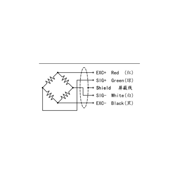
Rated sensitivity is 1.5 +/-0.05 mV/V, with input resistance 380 +/-30 ohms and output resistance 350 +/-5 ohms. The bridge needs 5-12 V DC excitation and lists a 3 m cable. Confirm any amplifier or transmitter and its connection to the RTU or logger. Establish a documented baseline under known line conditions and verify scaling and timestamps. Changes in line load are not, on their own, a calibrated ice-thickness result or a ready-made alarm threshold.
Icing interpretation and the monitoring package
Q1. Does the load cell measure ice thickness directly?
It measures force in the installed load path. A thickness estimate needs a defined relationship to conductor geometry and other relevant line conditions, with suitable baseline and validation. Request the monitoring-system method separately from the sensor specification.
Q2. Does a high-voltage tower application mean the sensor is an insulator?
No dielectric or insulation rating follows from that application description. The device is part of a reviewed mechanical and electrical assembly. Submit the applicable utility requirements and obtain the necessary assembly evidence before approving its use.
Q3. Is an RTU-ready transmitter included?
The specification establishes a raw mV/V bridge, not a particular RTU protocol or conditioned output. Identify any amplifier, transmitter, power arrangement and enclosure on the quotation. Verify the final logged engineering-unit value after the complete channel is installed.
