


 Chinese
 Spanish
 Russian
 Portuguese
 French
 German
 Indonesian
 Thai
 Vietnamese
 Arabic
 Italian
 Turkish
 Polish
 Japanese



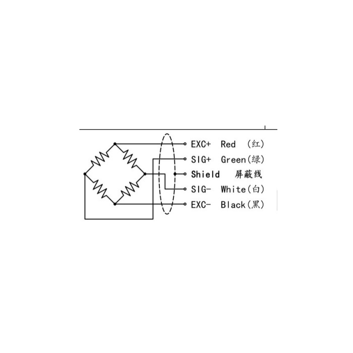
METRAVON MV-LC0130 is a radial tension sensor for yarn, metal wire and fabric-tape handling systems. Its bending structure has a fixed end and a radially loaded end, with a documented 10-50 kg family range. The indicated radial load is related to line tension through the actual guide arrangement, so the sensor and material path need to be specified together.
Keep the radial tension sensor mounting and loading point distinct
The reference drawing shows an M27 x 2 mounting section, an M5 designation at the loaded end and a 125 mm body-length reference. The cylindrical head is 34 mm in diameter. Obtain the guide attachment and force-application details before machining the machine bracket. Drawing lengths identify physical features, not an automatically valid calibration lever arm. Moving the guide along the loaded end can change the bending moment for the same radial force.
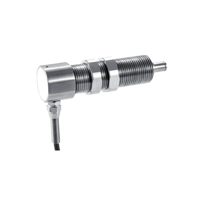
Convert the guide reaction using the real material path
Submit the incoming and outgoing line directions, guide or roller dimensions, normal tension range and peak events. A change in guide angle can change radial reaction even when line tension is unchanged. Bearing friction, material contact and any guide weight also need review. Establish the conversion with the assembled path and suitable references rather than relabelling a force display as yarn or wire tension. The 10-50 kg family label does not define a permitted line tension for every wrap angle.
| Item | Value | Selection notes |
|---|---|---|
| Family range | 10-50 kg | Size for radial reaction at the documented load point. |
| Mounting designation | M27 x 2 | Review bracket thickness and locking access. |
| Loaded-end designation | M5 | Confirm guide attachment and permitted engagement. |
| Length / head diameter | 125 / 34 mm | Use the complete drawing for clearances and cable exit. |
| Nominal bridge output | 1.5 +/-0.05 mV/V | The signal is not a built-in current-loop output. |
| Excitation / cable | 5-12 V DC / 3 m | Calibrate with the final routing and measuring electronics. |
Set the amplifier for the millivolt bridge and final cable
Rated sensitivity is 1.5 +/-0.05 mV/V, with 380 +/-30 ohms input resistance and 350 +/-5 ohms output resistance. Excitation is 5-12 V DC; the listed cable is 3 m long and 5 mm in diameter. Specify the conditioner input and any required PLC or data-logger output separately. Route the cable clear of the measured guide movement, then verify zero and span at the final controller using the intended force application point.
Test the tension range used by the machine
Select capacity from the greatest radial reaction, including startup, stopping and foreseeable material disturbances, while checking the smallest useful tension change. Compare readings at relevant guide positions and repeat a reference condition after unloading. Nonlinearity is listed as +/-0.05-0.1% FS, not an accuracy claim for the whole tension-control loop. Stainless-steel construction and IP65 are specified, with -20 to +70 deg C operation. No bandwidth or complete control-loop response is established by these entries.
Guide position and line-tension conversion
Q1. Is the measured radial force the same as the material tension?
Not in every guide arrangement. The two line directions and contact conditions determine how material tension produces radial load. Provide the path sketch and establish the conversion with the actual guide instead of assuming a one-to-one relationship.
Q2. Can the guide be moved along the shaft after calibration?
A changed force-application point can change the bending moment and scale factor. Obtain approval for the revised attachment and repeat the relevant reference checks. Preserve the loading geometry used for the accepted calibration.
Q3. Will the listed capacity prove that the control loop can handle a fast line?
Capacity addresses load, not the dynamic performance of the sensor, guide, amplifier and controller together. State line speed, disturbances and the response needed by the process. Confirm the complete channel before using it for a fast tension-control function.
