


 Chinese
 Spanish
 Russian
 Portuguese
 French
 German
 Indonesian
 Thai
 Vietnamese
 Arabic
 Italian
 Turkish
 Polish
 Japanese



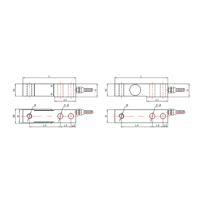
METRAVON MV-LC0123 is a cantilever beam load cell for platform, hopper and tank weighing, with a published capacity range of 50 kg to 10 t. One end is fixed and the other receives the load. The family uses different body sizes and load-connection threads across the range, so increasing capacity can require changes to the mounting plate and loading accessory.
Check the cantilever beam mounting size first
The following metric dimensions distinguish the principal body groups. They are useful for identifying a likely fit, but they are not a substitute for the complete drawing. Check the loading point, support clearance and cable exit as well as the bolt pattern. The lower-capacity and higher-capacity drawings also differ in the sensing-section construction.
| Rated load | Overall length | Hole centres | Load thread |
|---|---|---|---|
| 50 kg-2 t | 130 mm | 26 mm | M12 x 1.75 |
| 2.5-5 t | 171.5 mm | 38.1 mm | M18 x 1.5 |
| 6-10 t | 225.6 mm | 50.8 mm | M30 x 2 |
For a multi-support vessel, assess the highest reaction at any one support rather than assuming an equal share of the gross weight. Off-centre filling, an uneven base or restrained pipework can increase the force on one sensor. Describe these conditions when choosing the rating and the mounting arrangement. A larger sensor alone cannot correct a load path that bypasses the measuring point.
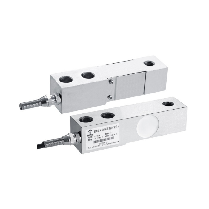
Performance values that affect the weighing system
| Characteristic | Listed value |
|---|---|
| Sensitivity | 2.0 ±0.05 mV/V |
| Excitation | 5-12 V |
| Non-linearity | ±0.03 to ±0.05% FS |
| Hysteresis / repeatability | ±0.03 / ±0.03% FS |
| Input / output resistance | 380 ±30 / 350 ±5 ohm |
| Operating temperature | -20 to +70 °C |
| Safe overload | 150% FS |
| Protection | Confirm the IP65 or IP66 version for the intended installation. |
Non-linearity, hysteresis and repeatability are separate error characteristics. Do not quote the smallest number in the table as the accuracy of a complete scale. Specify the required weighing performance at the actual working loads and check the installed system with suitable reference loads.
Mounting and first-load checks
- Identify the fixed end and loading end from the selected drawing. The sensing section and loaded end need clearance to deflect without touching the base or guards.
- Check that the loading foot or attachment seats correctly. Its thread, contact geometry and height must suit the chosen capacity group.
- Route the cable so movement at the loaded end cannot pull on it. Follow the supplied bridge wiring identification and the instrument grounding instructions.
- With the complete platform or vessel installed, record zero and apply known loads at the required positions. Investigate uneven readings and poor zero return before releasing the equipment.
Replacement questions
Q1. Can the 2 t and 5 t versions use the same bracket?
Not without a drawing check. The listed overall length increases from 130 to 171.5 mm, fixing-hole centres change from 26 to 38.1 mm, and the load thread changes. Assess the bracket, bolt sizes and load position before deciding whether a modification is practical.
Q2. Will the existing indicator work with several sensors?
Verify its bridge excitation, minimum permitted load resistance and input range against the sensor count and wiring arrangement. A shared nominal 2 mV/V sensitivity does not by itself establish compatibility or eliminate corner adjustment and calibration.
Send the existing bracket drawing for MV-LC0123 selection, together with empty and full vessel weights, support positions, the instrument details and any washdown or corrosion exposure. This allows the quotation to identify the body size, material and protection version rather than capacity alone.
