


 Chinese
 Spanish
 Russian
 Portuguese
 French
 German
 Indonesian
 Thai
 Vietnamese
 Arabic
 Italian
 Turkish
 Polish
 Japanese


Radar Level Transmitter Nozzle Design: Height, Diameter and Clearance
Design rule. A radar level transmitter nozzle is part of the measurement path, not just a mechanical connection. Its diameter, length, internal finish and position determine whether the antenna sees the product or the tank. There is no universal height-to-diameter ratio that is safe for every antenna: use the manufacturer’s antenna-specific limit, then check the beam against the actual vessel geometry.
Start with four dimensions, not the flange size
Before selecting a DN50, DN80 or DN100 connection, establish:
the antenna’s required minimum opening and its reference plane;
the distance from that reference plane to the highest product surface;
the nozzle’s unobstructed internal diameter after gasket and weld allowances;
the beam envelope at the product, including the tank wall, agitator, coils and fill stream.
A large flange does not guarantee a large measuring aperture. Reducers, a raised-face gasket or a weld protruding into the bore can create the narrowest and most reflective section.
Worked beam-clearance example
For an antenna with a 10° total beam angle, the nominal radius at distance h is:
r = h × tan(10° ÷ 2)
At a 12 m measuring distance:
r = 12 × tan 5° = 1.05 m
If the engineering standard also requires 0.30 m clearance from a tank wall, place the antenna centerline at least 1.35 m from that wall under this simplified free-space model. Then check every other obstruction at its own distance, not only at the tank bottom.
This calculation does not mean that no energy exists outside the nominal cone, or that an echo inside it will always fail. It is a layout screen. The antenna datasheet and an echo review remain necessary. A narrower high-frequency beam can reduce the clearance demand, but it cannot correct a nozzle that already blocks the antenna.
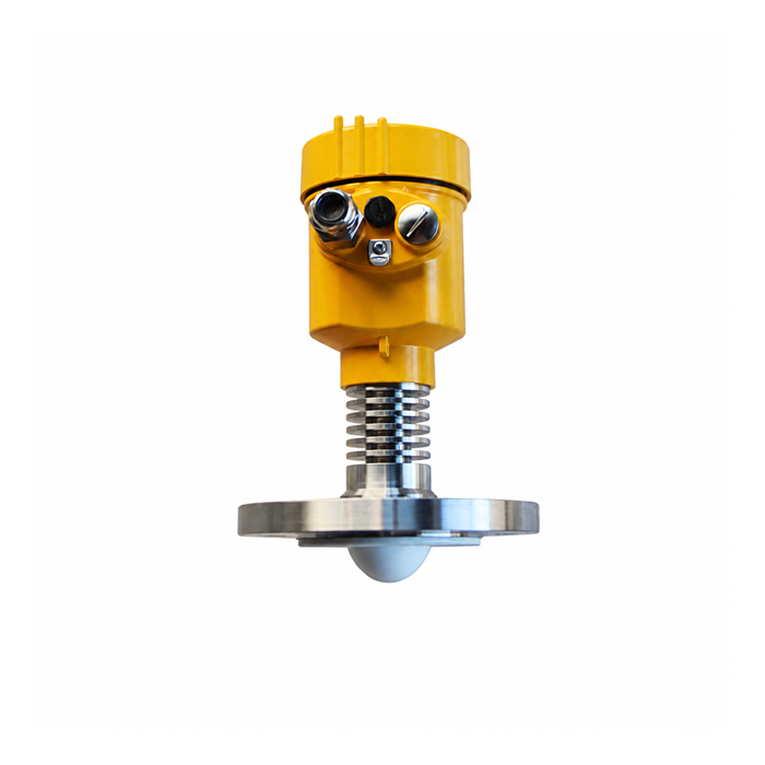
What changes when the nozzle is long
A recessed antenna can illuminate the nozzle wall. The result may be a strong near echo, ringing, attenuation, or an apparently stable reading that locks onto the wrong target. Increasing gain or extending a suppression map is not a mechanical repair.
| Observation on the drawing | Why it deserves review | Better design action |
|---|---|---|
| Antenna face sits above the nozzle outlet | Product path begins inside a reflective pipe | Use an approved antenna extension or revise the nozzle |
| Long small-bore nozzle | Multiple internal reflections and restricted beam | Check the exact model’s length/diameter limit |
| Nozzle close to wall | Wall enters the beam at lower levels | Relocate or select a suitable narrower beam |
| Nozzle beside fill inlet | Falling product and splashes cross the signal | Move away from the stream or provide a suitable stilling arrangement |
| Gasket enters the bore | A near-field discontinuity | Specify correct gasket ID and installation control |
| Sloped nozzle on a dished head | Antenna may not face the surface as intended | Check allowable tilt and the actual reflection geometry |
The safest sentence for a purchase specification is not “short nozzle preferred.” It is: “Nozzle inside diameter, projection, antenna recess and permitted tilt shall be checked against the selected instrument’s published installation drawing.” That makes the check assignable and auditable.
When a stilling well helps—and when it creates another problem
A stilling well can isolate the measurement from turbulence and provide a controlled path in an existing chamber. It must be open to the process, adequately vented, correctly sized for the antenna or probe, and free from internal steps. The level inside must follow the vessel without an unacceptable delay.
For non-contact radar, follow the antenna manufacturer’s requirements for pipe diameter, joints and through-holes. For guided-wave radar, check probe-to-wall clearance and whether the probe can contact the pipe during filling or agitation. A pipe that is suitable for a still liquid may be unsuitable for a viscous, crystallizing or fouling product because the annulus can plug.
Do not confuse a bypass chamber with a stilling well. Their density, temperature and venting behavior can differ, and the chamber level may lag or differ from the vessel.
A nozzle schedule that procurement can actually use
Add these columns to the tank nozzle schedule: service and tag; selected instrument model and antenna; flange and gasket specification; nominal and minimum bore; nozzle projection above and below the vessel; antenna insertion or extension; reference plane; distance to wall and internals; maximum product level; and the manufacturer drawing used for the review. “DN80, one per tank” is not enough information to build a reliable measuring point.
On a replacement project, photograph the bore and measure it rather than relying on an old isometric drawing. A previous modification may have added a reducer, liner or damaged section.
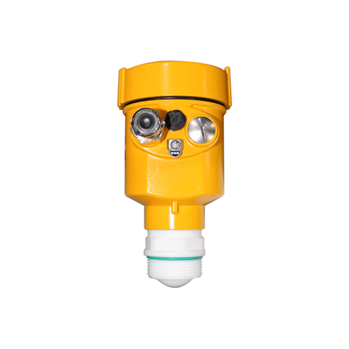
A redline review that ends in a decision
Print the vessel section and mark the antenna reference, nozzle outlet, maximum level, beam envelope and every obstruction. Then assign one of four dispositions: acceptable with the cited instrument drawing; acceptable with a defined antenna extension; requires nozzle relocation; or cannot be resolved without changing the measurement arrangement. Record the reviewer and document revision.
For an existing nozzle, add an empty-tank echo curve to the package. The curve cannot validate every product condition, but it can reveal a strong near reflection before a new transmitter is ordered. If the proposed solution depends on suppression, write down which echo will be suppressed and how the team will prove that a real high level is not suppressed with it.
Field questions before fabrication
Q1. Can the nozzle be extended later if there is a false echo?
Sometimes an approved antenna extension solves the problem, but adding ordinary pipe changes the aperture and may worsen it. Treat the change as an instrument redesign, not a plumbing alteration.
Q2. Is a larger nozzle always better?
No. Mechanical pressure rating, available space, antenna compatibility and cost still matter. The correct opening is the one validated for the antenna, not simply the largest available.
Q3. Can the transmitter sit at an angle to reach a clear part of the tank?
Only within the device’s permitted alignment. Tilting changes the path and may reduce the returned signal; verify the intended mounting rather than improvising on site.
Q4. What should be inspected before closing the tank?
Bore, weld and gasket protrusion, antenna position, verticality, foreign material, and the distance to internals. Save photographs against the tag number.
