


 Chinese
 Spanish
 Russian
 Portuguese
 French
 German
 Indonesian
 Thai
 Vietnamese
 Arabic
 Italian
 Turkish
 Polish
 Japanese


Wastewater basin level measurement is useful only when the observed surface matches the control duty. A radar may see foam, floating material or turbulent water near an inlet instead of the representative liquid level needed for pumping. Decide what the controller must follow before accepting a mounting position or adjusting filtering.
Find a view of the water that survives normal operation
Plot inlet cascades, aerators, ladders, lifting chains and pump zones on a basin section. Check the measuring path at the lowest and highest required surfaces. A clear view during a maintenance shutdown may be obstructed by a moving chain, foam accumulation or inflow during operation.
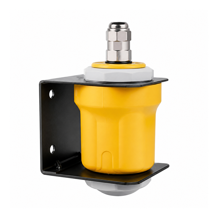
The METRAVON MV-RD12T uses a 42 mm PVDF lens assembly for atmospheric water-level applications. Its non-contact arrangement avoids an immersed probe, but the lens, cable seal and bracket still need assessment for wastewater gases, splash and cleaning chemicals.
Test wastewater basin level measurement against the intended target
If the pump sequence needs liquid beneath persistent foam, demonstrate that measurement under the actual foam condition. Do not assume a fixed correction from foam height to water level. Save the echo and process state when the target changes so maintenance staff can distinguish a surface change from an instrument fault.
| State | Compare | Reason |
|---|---|---|
| Quiet basin | Radar distance and a safe level reference | Establishes the datum and initial scaling. |
| Pump start | Raw reading, controller value and pump status | Separates surface drawdown from signal or input faults. |
| Foam event | Observed surface and returned target | Shows whether the indication still supports its assigned duty. |
| Rapid inflow | Level rise and total control response | Checks that filtering does not conceal a meaningful rise. |
Keep sensor filtering separate from pump sequencing
Damping changes how quickly the measured value follows the surface. Controller deadband and minimum run time address pump cycling. Adjusting all three without recording their roles can make a steady display look acceptable while delaying the required pump action.
During commissioning, verify local distance, calculated level and the PLC or RTU input separately. Define the response to lost echo, communication timeout and power recovery. Select the actual 4-20 mA or RS485/Modbus RTU electronics and obtain its fault indications; do not assume all output options are present in one instrument.
Flood and inspection questions
Q1. Does the IP68 listing permit measurement while submerged?
No. Enclosure protection does not establish a usable radar path through water covering the antenna. Review flood depth and duration for the supplied assembly, keep electrical joints out of the flood zone where possible, and define how an inundated measurement is marked unavailable.
Q2. Can the pump-control signal also provide independent high-level protection?
Several alarms derived from one sensor share that sensor's failure modes. Where the risk assessment calls for independence, use a separately assessed protective path and test it separately from the normal control loop.
Q3. What should maintenance record before cleaning?
Record the as-found lens condition, mounting position, raw reading and echo before changing anything. Compare the result after approved cleaning. This identifies whether deposits are affecting the signal and helps set an evidence-based inspection interval.
Summary
For a wastewater level application review, send the basin section, foam behaviour, pump sequence and flood exposure. Accept MV-RD12T only against the required target and a tested response to unavailable measurement.
