


 Chinese
 Spanish
 Russian
 Portuguese
 French
 German
 Indonesian
 Thai
 Vietnamese
 Arabic
 Italian
 Turkish
 Polish
 Japanese


METRAVON Radar Level Measurement for Oil Tanks: Leakage, Fixed Offset and Low-Level Echo Problems
Radar level transmitters are widely used for crude oil, diesel, fuel oil, lubricants and many other hydrocarbon liquids. Unlike hydrostatic measurement, radar directly measures the distance to the product surface, so liquid density is normally not a direct measuring variable.
Oil applications have their own challenges. Some hydrocarbons have relatively low dielectric properties, which can reduce surface reflection. At low level, the tank bottom may become a strong competing target. Mechanical sealing, reference height and PLC scaling can also create problems that look like radar inaccuracy.
Why Oil Tanks Need Special Attention
Compared with water, some oils and hydrocarbon products return a weaker radar echo. Selection should therefore consider product composition, dielectric behavior, minimum operating level, tank-bottom construction, measuring distance, vapor space and internal structures.
Process-Connection Leakage Is a Mechanical Problem First
If liquid appears around a process connection, identify its source and treat suspected leakage under the site containment and isolation procedure. Do not loosen or retighten a live connection without authorization. Echo or span settings cannot repair a sealing problem.
Possible causes include:
- Incorrect or damaged gasket installation;
- Seal material incompatible with the product;
- Permanent deformation or aging of the seal;
- Uneven clamp or flange loading;
- Temperature or pressure outside the seal rating;
- Damaged sealing surfaces.
FKM, PTFE and Other Seal Materials Must Be Selected by Chemistry
There is no universal “oil-compatible” gasket. Confirm the exact product, aromatic content, additives, temperature, pressure and sealing geometry before selecting FKM, PTFE or another material.
Do not use PTFE thread tape as a substitute for the correct gasket on a sanitary clamp or dedicated sealing face. Thread tape is only appropriate on compatible threaded-sealing applications.
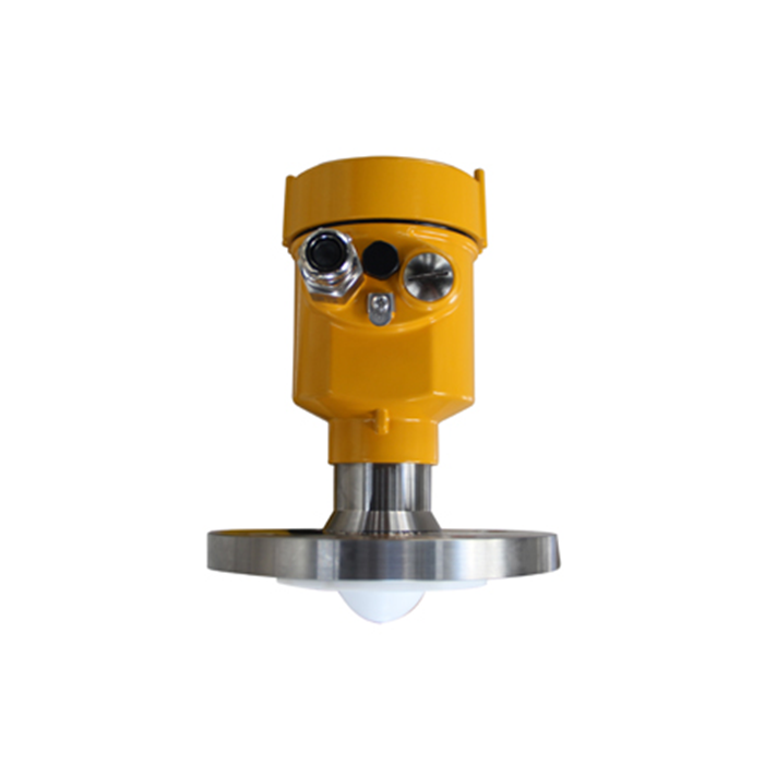
What If Liquid Has Entered the Electronics Compartment?
Do not simply dry the enclosure and return the transmitter to service. Check terminals, insulation, circuit-board condition, process sealing and cable glands. In hazardous areas, follow the maintenance rules of the certified product and site procedures.
Diagnostic Codes Such as “E14” Are Model-Specific
Fault codes are not standardized across radar manufacturers. An E14 code may mean something completely different on another model. Always use the diagnostic table for the exact instrument before linking a code to water ingress, loss of echo or electronics failure.
Check the reference before correcting a constant offset
If manual gauging and radar follow the same level trend but remain separated by a nearly constant offset, check the measurement reference before changing radar signal parameters.
Verify:
- Radar reference plane;
- Empty-distance setting;
- Full-scale configuration;
- Tank reference height;
- Manual gauging reference point;
- PLC/DCS 4-20 mA scaling;
- Engineering units and datum.
Separate Distance Accuracy from Level Conversion
When an independently verified distance agrees with the radar distance, trace the conversion through reference height, local level, current output and PLC scaling. This helps locate the disagreement but does not certify every part of the device; output configuration or electronics can still require investigation.
Can a Tilted Flange Cause Error?
A significantly tilted free-space radar can weaken the useful surface echo or direct more energy toward the wall and internals. It may reduce tracking stability, but a small installation angle does not automatically explain a large constant error.
Large fixed offsets should first trigger a reference-height and scaling check.
Why Low Level Can Cause a Sudden Jump to Zero
With low-dielectric products, not all radar energy is reflected at the liquid surface. Some can continue through the product and reach a metal tank bottom.
At low level, the transmitter may see a weak product-surface echo close to a strong bottom echo. If target tracking changes from the product surface to the tank bottom, the result may be a sudden low reading, a fixed near-zero value or intermittent loss of echo.
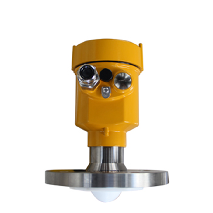
Do Not Simply Shorten the Range
Reducing the maximum measuring distance may exclude part of the bottom region, but it can also remove the low-level range that the process genuinely needs. Confirm the minimum required level and inspect the echo curve before narrowing the active range.
Tank-Bottom Echo Suppression Requires Care
Fixed-echo mapping is useful for permanent structures, but a low product surface can be very close to the tank-bottom echo. Learning the bottom blindly may also suppress the real low-level signal.
Confirm the actual level, save the echo curve, identify the product and bottom targets, and then apply the instrument's approved fixed-echo or bottom-tracking functions if appropriate.
Does 80GHz Solve Every Low-Dielectric Oil Application?
No. 80GHz is valuable for narrow beam width, compact antennas and target separation, but the basic challenge in a low-dielectric liquid remains the strength of the surface reflection. Range, antenna design, tank bottom and the transmitter's signal-processing capability all matter.
When to Consider Guided Wave Radar or a Stilling Well
Guided wave radar may be useful for selected clean low-dielectric liquids because the signal travels along a rod, cable or coaxial probe. Probe coating, corrosion, mechanical load and installation geometry still require review.
A properly designed stilling well can also provide a defined free-space radar path in some oil tanks, but the dimensions, internal continuity, openings and buildup condition must be suitable for the radar design.
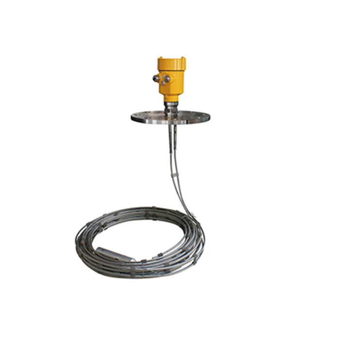
Process Measurement Is Not the Same as Custody Transfer
A general process radar may be suitable for process control, pump control, high/low alarms and inventory trending. High-accuracy inventory management or custody transfer can require a different class of radar, tank calibration tables, temperature measurement, volume correction and project-specific metrology requirements.
Millimeter-level distance accuracy does not automatically mean the final tank volume or mass is accurate to the same equivalent level.
Do Not Use ±1mm as a Universal Acceptance Criterion
Process radar, inventory radar and custody-transfer systems are designed to different performance levels. Acceptance criteria should come from the specific datasheet, tank geometry, project specification and agreed test method.
Hazardous-Area Requirements Must Be Declared Early
Hydrocarbon tanks may contain flammable vapor. Provide the area classification, gas group, temperature class and required certification such as ATEX, IECEx or local equivalents during the RFQ stage.
An IP rating is not a substitute for hazardous-area certification.
High-High Overfill Protection May Need an Independent Layer
A continuous radar can provide high-level alarms, but whether it can also serve as the independent overfill-protection layer depends on the site's risk assessment and safety architecture. Critical tanks may require an independent high-high switch or separate protection channel.
Quick Troubleshooting Table
| Symptom | Check First |
|---|---|
| Process connection leaks | Gasket, chemical compatibility, loading, temperature and pressure |
| Constant level offset | Reference height, empty/full settings, PLC scaling, manual-gauge datum |
| Low-level jump to zero | Low-dielectric product echo vs tank-bottom echo |
| High-level abnormality | Minimum distance, condensation, near-field buildup |
| Local display correct, PLC wrong | 4-20 mA loop and control-system scaling |
Recommended Troubleshooting Sequence
- Confirm the real oil level with an independent method;
- Compare local radar indication with the control-system value;
- Verify reference height and scaling;
- Review the echo curve;
- Inspect antenna and process connection;
- Evaluate low-level product and tank-bottom echoes;
- Change configuration only after the cause is understood.
Questions before replacing an oil-tank radar
Q1. Should a leaking process connection be corrected through calibration?
No. Treat suspected leakage as a containment issue and follow site isolation and inspection procedures. Verify the source, seal materials, assembly condition and pressure or temperature limits. A configuration change cannot repair a damaged sealing face or establish that an enclosure contaminated by product is safe to reuse.
Q2. What distinguishes a reference offset from a ranging fault?
Compare an independent surface distance with the radar distance at the documented reference plane, then check the conversion to local and PLC level. A constant difference suggests where to investigate but does not prove the hardware is healthy. Do not apply an offset before resolving datum, units and scaling.
Q3. Why can a light oil read correctly until the tank is nearly empty?
A weaker surface return may compete with exposed internals or the tank-bottom echo as level falls. Capture the selected target and actual surface reference around the failure point. Verify the required low-level range before narrowing the measuring window or suppressing a bottom return close to the real surface.
Q4. What is required before ordering a replacement?
Provide the exact product, normal and design conditions, existing model and output, nozzle drawing, reference dimensions and fault evidence. Include seal details and hazardous-area requirements. Match the replacement to the verified cause and installation rather than using a similar appearance or headline accuracy as the compatibility test.
Field Troubleshooting Summary
Oil-tank radar problems usually fall into three groups: process sealing, measurement-reference errors and weak/competing echoes at low level. Treating these separately prevents unnecessary recalibration and makes troubleshooting much faster.
Keep seal inspection findings separate from level-reference and echo records when requesting a replacement assessment. Submit oil-tank fault information
