


 Chinese
 Spanish
 Russian
 Portuguese
 French
 German
 Indonesian
 Thai
 Vietnamese
 Arabic
 Italian
 Turkish
 Polish
 Japanese


NAMUR NE43 and the 4-20 mA Standard: Reading the Signal Honestly
The 4–20 mA signal looks simple — four milliamps at zero, twenty at full scale — but the part that makes it safe is the part most people never set: the alarm behaviour outside that range. NAMUR NE43 defines what a transmitter should do when it is slightly past the range and when it has genuinely failed, so that a control system can tell the difference between "a bit over full scale" and "the transmitter is broken." That distinction is what keeps a fault from being read as a process value.
The live zero and its diagnostic limits
A 4 mA live zero separates a valid lower-range value from loss of loop current. A zero-current indication can result from a broken wire, loss of power or another circuit fault. Currents slightly below 4 mA can still represent valid underrange; they are not all hardware failures. Interpret them with the documented transmitter and input thresholds.
The NAMUR NE43 ranges
NAMUR NE43 defines three regions around the normal 4–20 mA range:
| Current region | Common NE43 interpretation | Receiving-system action |
|---|---|---|
| At or below 3.6 mA | Low failure indication; 0 mA can also mean loss of power or an open circuit | Mark bad quality and apply the documented fault response |
| Above 3.6 and below 3.8 mA | Separation region between failure and measurement | Use documented thresholds and hysteresis; do not call it a valid low process value by default |
| 3.8 to below 4.0 mA | Extended measurement or low saturation region | Show underrange status separately from fault |
| 4.0 to 20.0 mA | Nominal configured measurement range | Scale to the assigned variable and units |
| Above 20.0 to 20.5 mA | Extended measurement or high saturation region | Show overrange status separately from fault |
| Above 20.5 and below 21.0 mA | Separation region | Apply documented input handling |
| At or above 21.0 mA | High failure indication | Mark bad quality; do not interpret as a valid high level |
Check the exact transmitter settings, input thresholds, tolerances and hysteresis. The commonly used separation is measurement including saturation within 3.8–20.5 mA, with failure indication at or below 3.6 mA or at or above 21 mA. A high current does not uniquely identify a cable short; diagnose the circuit and device status.
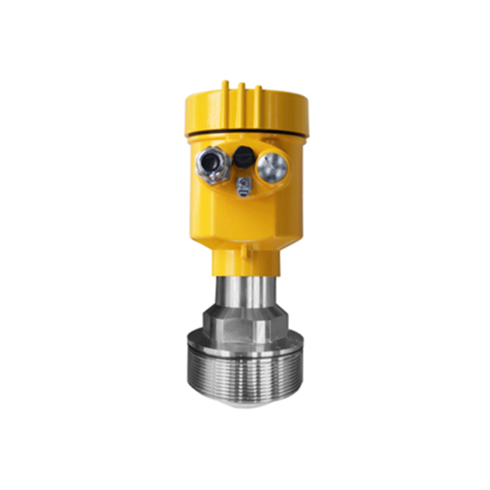
Saturation vs failure signal
When the process goes slightly past the range, the transmitter saturates — it clamps at a value just outside 4 or 20 mA (for example 3.9 or 20.3 mA) but keeps reporting. When the transmitter detects its own fault, it drives the loop to a failure current (for example 3.6 mA or 21 mA) that the control system is configured to read as an alarm.
A 21 mA signal may represent a configured device fault rather than an overflowing tank. Set high or low failure current from the application requirements, device safety manual where applicable and receiving logic. Neither direction is universally safer. An undiagnosed fault can still leave a plausible current, so NE43 is not complete failure coverage.
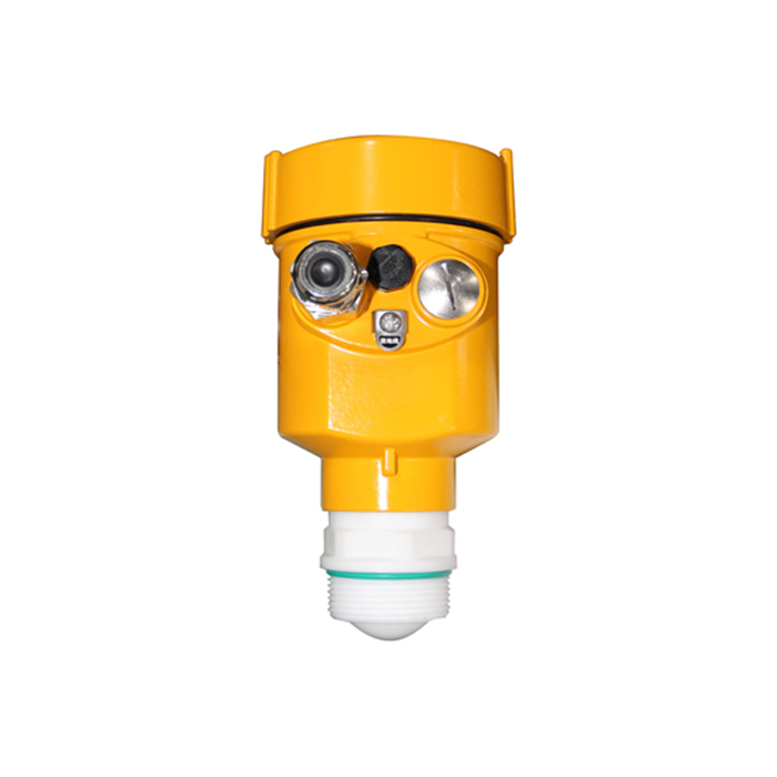
Reading the signal honestly in the DCS
The value of NE43 is only realized if the control system is configured to use it. Three settings matter:
Range in engineering units. The 4 mA and 20 mA points must map to the correct zero and span, in the correct units.
Diagnostic thresholds. Configure bad-quality detection outside the documented measurement region, including tolerances and hysteresis. Process high and high-high alarms are separate engineering-unit setpoints; valid underrange or overrange may also need an operating alarm.
Failure direction. Confirm whether the transmitter fails high or low, and set the trip logic to match — this is a safety decision, not a cosmetic one.
Questions technicians ask
Q1. Is 4-20 mA still used?
It remains a widely used process interface. HART can add digital communication to a compatible current loop, while other digital buses use their own physical layers; they do not all ride on a 4–20 mA pair.
Q2. What does a reading of 3.8 mA mean?
It commonly lies at the low end of the extended measurement or saturation region. Check device status, configuration and input tolerance before assigning its quality. A configured low fault is normally at or below 3.6 mA; exact equality matters.
Q3. Why do some transmitters fail at 21 mA instead of 3.6 mA?
The chosen failure direction depends on the application, device limits and safety requirements. Configure the receiver to recognise both required fault conditions; a low-current fault is not universally the preferred safety setting.
Q4. Do I set my DCS alarm at 20 mA?
Distinguish the process alarm from the diagnostic alarm. A high-high process limit may be below full scale and needs its own setpoint. Fault-current thresholds identify invalid measurement; they must not replace the process alarm or trip logic.
Related technical guides
- Radar Level Transmitter Output Signals: Choosing the Right One
- Radar Level Transmitter Accuracy: What the Datasheet Number Does Not Tell You
Discuss your measurement application with METRAVON
