


 Chinese
 Spanish
 Russian
 Portuguese
 French
 German
 Indonesian
 Thai
 Vietnamese
 Arabic
 Italian
 Turkish
 Polish
 Japanese


Guided Wave Radar vs Non-Contact Radar: The Dielectric Decides
Both technologies use electromagnetic measurements, but their implementations and signal paths differ. Guided-wave radar guides a signal along a contacting probe; free-space radar radiates through an antenna. Compare reflection, probe contact, mechanical loading, coating, process ratings and the required interface or surface result. There is no universal dielectric cutoff or guaranteed immunity to foam.
The same physics, two different geometries
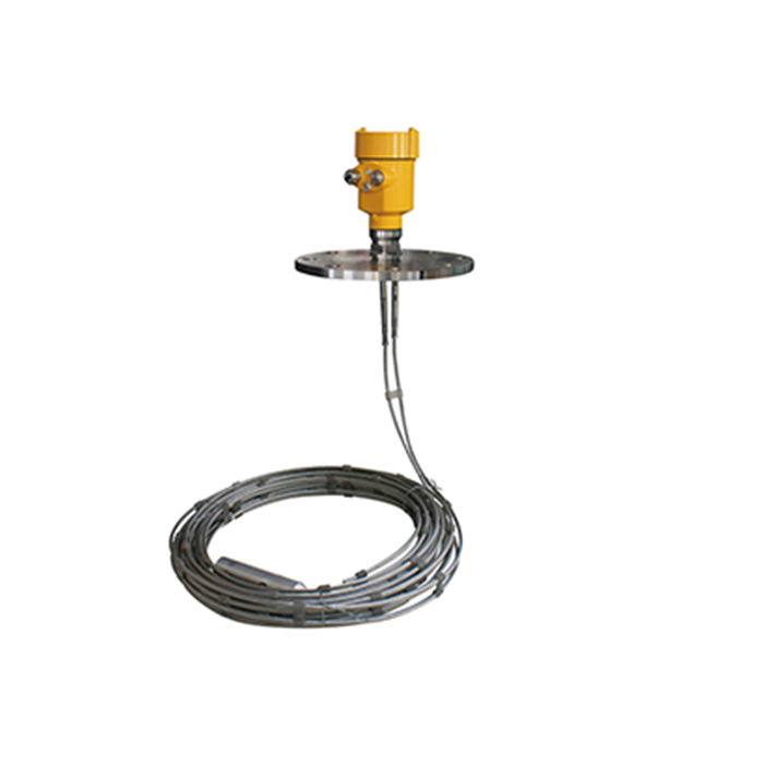
A guided-wave radar, also called TDR or time-domain reflectometry, launches a signal along a transmission-line probe. The electromagnetic field extends around the conductor; it is not confined inside a solid metal rod. A change in the surrounding medium changes impedance and can produce a reflected signal.
An idealised lossless, non-magnetic boundary model illustrates an amplitude reflection coefficient. Actual guided-wave behaviour also depends on probe geometry, conductivity, frequency content and losses:
R = (√ε₁ − √ε₂) / (√ε₁ + √ε₂)
Using illustrative permittivities of 1 and 80, the ideal coefficient is about -0.80 in amplitude, corresponding to about 64% reflected power. These assumed values are not a guarantee for an actual probe or microwave process measurement.
Using an illustrative product permittivity of 2.1 gives an amplitude coefficient of about -0.18 and roughly 3.4% reflected power. Do not treat this static assumed value as a verified property of every diesel formulation at the operating frequency.
Guiding the signal can improve usable return in some low-reflection duties, but it does not eliminate attenuation or deliver every reflected signal intact. A suitable free-space design can also measure selected weak-reflection products. Evaluate actual instrument limits and evidence.
| Property | Guided-wave radar | Non-contact radar |
|---|---|---|
| Signal path | Along a contacting transmission-line probe | Radiated through a free-space antenna |
| Product sensitivity | Probe, dielectric/conductivity and coating | Reflection, antenna and measuring path |
| Foam and vapour | Model- and process-dependent | Model- and process-dependent |
| Interface duty | Available on suitable configurations | Usually upper-surface measurement in ordinary level service |
| Mechanical design | Probe length, clearances and loads | Beam, nozzle and antenna arrangement |
| Ratings and performance | Verify the complete ordered assembly | Verify the complete ordered assembly |
Dielectric constant, the number that decides
Product dielectric information can help assess reflection, but it is not the only deciding input. Include conductivity, temperature, coating, required range and the complete mechanical arrangement.
| Product information | What to establish |
|---|---|
| Low-permittivity liquid | Verified range of properties and actual signal margin |
| Conductive or corrosive liquid | Full material compatibility and probe/antenna suitability |
| Two liquid phases | Upper-layer transmission, thickness and interface definition |
| Foaming product | Required measured boundary and worst-condition tracking |
| Changing mixture | Credible composition range and representative test evidence |
Do not reject all free-space radar below a universal permittivity of two. Compare purpose-suitable configurations and evidence rather than a generic material pass/fail chart.
Interface measurement and its additional conditions
A suitable guided-wave configuration can report the upper surface and a lower interface when the upper layer transmits enough signal and both returns can be resolved. Other interface principles also exist; guided wave does not have a monopoly on the measurement.
The ideal boundary coefficients illustrate contrast, not guaranteed interface capability. The upper product changes propagation time and attenuation, so configuration may require its dielectric information as well as the permitted layer thickness and probe zones.
Three conditions have to be met, and projects fail when one of them is skipped.
- Suitable product contrast and transmission. Use the selected model limits, not a universal ratio or difference between dielectric constants.
- A defined interface. An emulsion can be a transition region rather than a line. Define the required boundary or profile and assess suitable instrumentation and sampling; do not claim that every emulsion is unmeasurable.
- A probe long enough to reach both. The probe has to pass through both layers and it must not stop in the upper one. A probe that ends in the oil reports the oil surface and nothing else.
Ordinary surface radar is normally specified for the upper reflecting surface, not a submerged interface. Any claimed lower-layer measurement needs a purpose-specific design and validation.
Where the probe becomes the problem
The contacting probe adds maintenance and mechanical considerations to the signal assessment.
Coating. Deposits can change impedance, attenuate signals or bridge probe gaps. Behaviour depends on probe design and the deposit. Review actual cleanability and diagnostic performance rather than a universal ranking.
Abrasion. Falling solids and bulk-material forces can damage a probe or its support. Check the fill stream, mechanical loads and permitted anchoring. Non-contact measurement avoids an immersed or hanging probe but still needs impact protection.
Corrosion and hygiene. Verify all exposed materials and the complete cleaning arrangement for either technology. A flush non-contact lens still presents exposed surfaces, seals and a connection that must be cleaned and qualified.
| Service | Contacting-probe review | Non-contact review |
|---|---|---|
| Viscous or coating product | Deposit and mechanical loads | Antenna/nozzle deposits and cleaning |
| Abrasive solids | Wear, fill impact and support loads | Antenna position, dust and impact |
| Hygienic process | Cleanable probe and connection | Cleanable antenna and connection |
| Low-reflection liquid | Actual model and probe limits | Actual model and antenna limits |
| Tall vessel | Approved length and loading | Rated range and path clearance |
Probe types and what each is for
A guided-wave transmitter is only as good as its probe, and the probe is selected from the product, not from the electronics.
| Probe arrangement | Checks required |
|---|---|
| Single rod | Length, wall clearance, coating and mechanical loading |
| Twin rod or cable | Bridging, product movement and approved installation |
| Coaxial | Product exchange, plugging and transmission-line geometry |
| Flexible cable | Loads, anchoring if required, clearance and product movement |
| Segmented or insulated construction | Approved joints, material integrity and specific measurement limits |
Select the probe against the actual duty and installation instructions. Minimum clearance, length, centring and anchoring are model-specific; do not copy a universal 100 mm rule.
Where non-contact radar is still the right answer
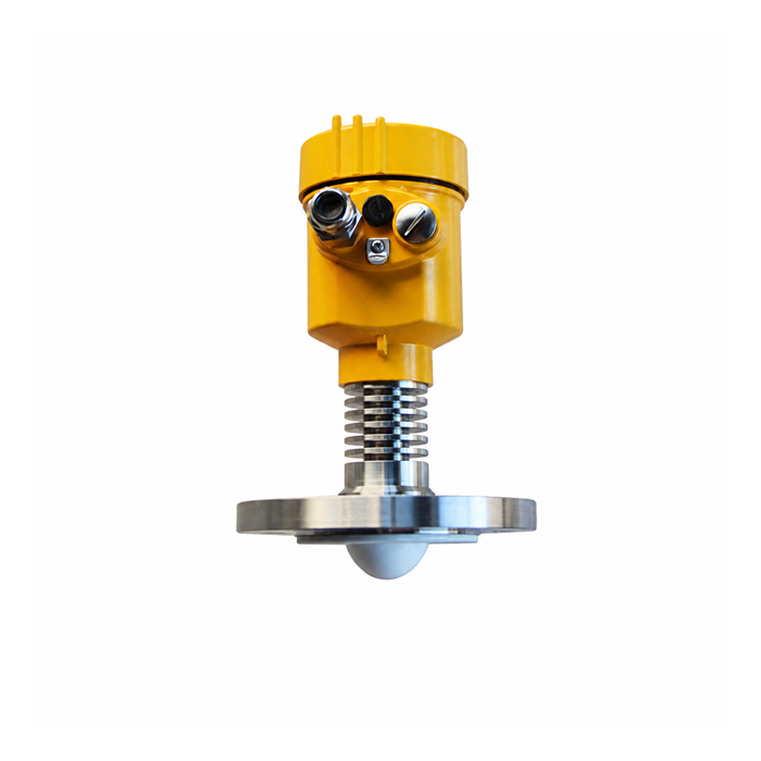
Non-contact radar avoids a probe extending through the product. It can still face vapour, deposits and corrosion at the antenna or connection, and it needs a suitable reflection and mounting arrangement.
The cases where it wins decisively are:
- Hygienic and aseptic service. Assess the complete cleanable connection and required evidence; a clamp fitting or smooth face alone does not establish hygiene.
- Abrasive and granular solids. Removing the contacting probe can reduce direct wear, while antenna impact and deposits still require review.
- Viscous, crystallising or polymerising products. A probe becomes a seed for build-up.
- Long range in tall silos. Compare the actual non-contact range with the guided-wave length, loading, access and maintenance constraints.
- Tanks with agitators and internals. Both handle it, but non-contact avoids the probe being bent by a rag bundle.
Frequently asked questions
Q1. Does guided wave radar work in foam?
It can work in selected foaming duties, but the field is not confined inside the probe and foam or coating can still affect it. Validate which boundary is reported under the actual process conditions.
Q2. Can guided wave radar measure an interface?
Suitable configurations can measure an interface within their upper-layer, thickness and signal limits. Define any emulsion boundary explicitly and evaluate alternative profiling or reference methods where needed.
Q3. Does a guided-wave probe need a stilling well?
Not automatically. A probe guides the signal but does not hydraulically calm the liquid like a stilling arrangement. Review clearances, loading, chamber exchange and any required supports.
Q4. What is the maximum length of a guided-wave probe?
Use the selected model and probe limits. Permitted length, loading, support and measuring zones differ by configuration; one generic rod or cable length is not a purchasing specification.
Q5. Does build-up on the probe affect the reading?
Deposits can affect the signal and measured result, but tolerance depends on probe geometry and deposit properties. Review cleaning, bridging and diagnostics rather than assuming that every coating forces a change of technology.
Q6. Can a guided-wave transmitter be used in food and pharmaceutical production?
A suitable probe and connection can be used when materials, cleaning, sterilisation and qualification requirements are met. A non-contact alternative also needs assessment of its complete exposed assembly.
