


 Chinese
 Spanish
 Russian
 Portuguese
 French
 German
 Indonesian
 Thai
 Vietnamese
 Arabic
 Italian
 Turkish
 Polish
 Japanese


If the displayed value falls while a tank fills, the instrument may be reporting distance rather than level. Ultrasonic distance-to-level conversion reverses the direction of change because the surface moves closer to a sensor mounted above it. Verify the variable before diagnosing a defective transmitter.
Work through one known movement
For a vertical measurement, let H be the sensor reference height above the level datum and d the measured distance. Level h is H minus d. In an illustrative installation with H = 4.0 m, a distance of 3.0 m represents 1.0 m level. When distance decreases to 2.0 m, level rises to 2.0 m.
The example describes geometry, not instrument accuracy. Its assumptions require a fixed reference and the intended surface. If the selected return comes from another object, a correct subtraction will still produce an incorrect process level.
Where ultrasonic distance-to-level conversion belongs
| Transmitted variable | Receiving-system treatment |
|---|---|
| Distance | Convert using the surveyed reference if level is required. |
| Level | Use the defined datum and units; do not subtract it as though it were distance. |
| Percentage | Establish which physical quantity and endpoints the percentage represents. |
| Volume | Check the conversion source and tank geometry before applying another volume calculation. |
Record the variable at each stage: local display, analogue or digital output, PLC input and operating screen. A transmitter can display one variable while its configured output carries another. Use the delivered documentation and settings rather than inferring output meaning from the display label.
Test the endpoints without bypassing controls casually
An authorised input simulation can check receiving scaling, but it does not prove the acoustic measurement. Identify the simulated part of the chain and manage any connected pumps or alarms through the site's procedure. Remove test overrides and verify the restored measurement afterward.
Use known low and high values to check direction, span and units. Reversing two endpoints may make the trend look right while leaving the physical reference wrong. Retain the expected engineering value for each test input.
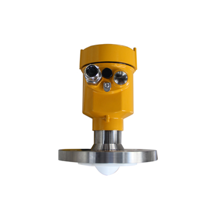
A radar change does not remove conversion work
The METRAVON MV-RD12 is a liquid radar alternative, not a cure for an incorrect receiving calculation. Specify the output variable and electronics version, then verify the conversion chain. If the existing sensor already reports valid distance, correct the integration problem before deciding whether a hardware change is needed.
Q1. Does a value labelled 100% always mean a full tank?
No. Identify the transmitted variable, engineering units and endpoint definition in the instrument configuration and receiving system. A distance percentage can increase as a tank empties, while a level percentage normally increases as it fills; neither establishes volume without the applicable vessel conversion. Record the physical condition assigned to each endpoint instead of using the display label as the specification.
Q2. Why does a second subtraction reverse the trend again?
The relationship h = H - d applies when the input is distance from the stated reference. If the transmitter already reports level, treating that value as distance changes the direction again and can also move the zero. Assign the conversion to one documented location. Compare local, transmitted and received values at two known conditions to check direction and span, and use additional points where a nonlinear conversion is involved.
Q3. What should be sent with a scaling enquiry?
Provide the sensor model, configured output variable, reference height and datum, endpoint settings, and local and receiving values at two known conditions. Include the relevant wiring or register information and the location of any distance, level or volume calculation. This record helps distinguish an integration error from a measurement fault before a replacement is specified.
Summary
Identify the variable before changing calibration. Provide the reference height, two known readings and output configuration when reviewing an MV-RD12 integration.
