


 Chinese
 Spanish
 Russian
 Portuguese
 French
 German
 Indonesian
 Thai
Thai Vietnamese
 Arabic
 Italian
 Turkish
 Polish
 Japanese

Engineering Summary
RS485 is a differential serial communication interface widely used in industrial field applications. It is commonly used to connect PLCs, RTUs, industrial instruments, Remote I/O devices, and industrial gateways. In practical projects, RS485 is frequently combined with Modbus RTU. Reliable communication depends not only on the A/B pair, but also on baud rate, device addressing, bus topology, termination, biasing, grounding, isolation, surge protection, and correct register interpretation.
What Is RS485?
RS485 is a differential electrical interface standard for industrial serial communication. It mainly defines the electrical characteristics of drivers and receivers, including differential signaling, bus loading, receiver thresholds, and multi-drop network behavior.
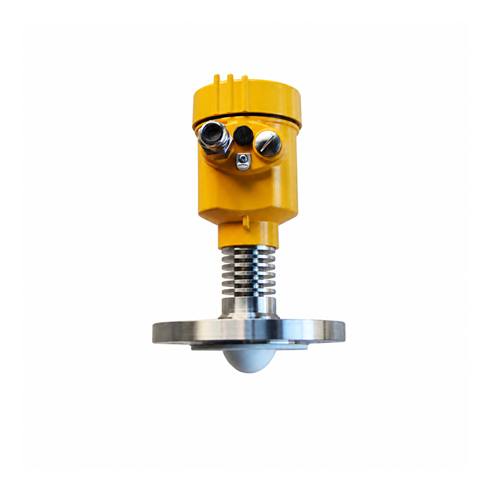
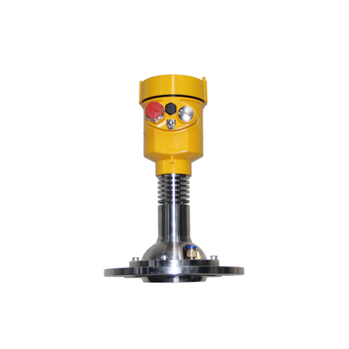
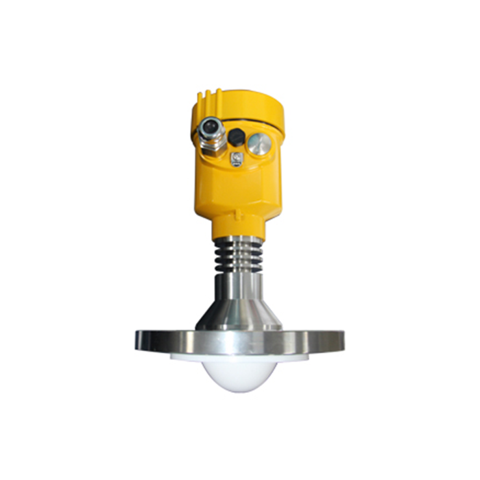
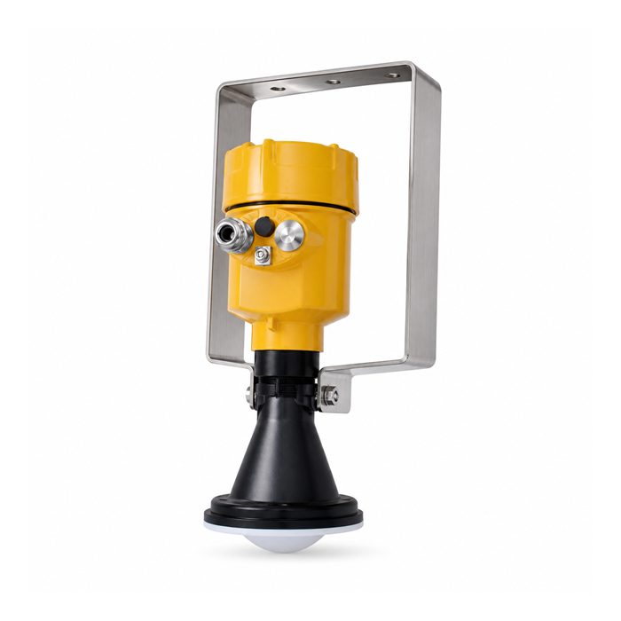
RS485 is widely used with radar level transmitters, weighing instruments, RTUs, Remote I/O, PLCs, and industrial gateways because it can provide robust wired digital communication in electrically noisy environments.
RS485 is a physical communication interface. Modbus RTU is a communication protocol.
Therefore, RS485 is not the same as Modbus RTU, although Modbus RTU over RS485 is one of the most common combinations in industrial automation.
Typical architectures:
Radar Level Transmitter → RS485 Modbus RTU → PLC
Weighing Indicator → RS485 Modbus RTU → PLC / DCS
Radar Water Level Sensor → RS485 Modbus RTU → RTU → 4G → MQTT / HTTP Server
How Does RS485 Differential Communication Work?
The core feature of RS485 is differential signaling. A typical 2-wire RS485 bus uses one twisted pair, commonly labeled A and B.
The receiver does not rely on the absolute voltage of a single conductor relative to ground. Instead, it detects the voltage difference between the two conductors:
Vdiff = VA − VB
If external electromagnetic noise couples similarly onto both conductors, the common-mode component is reduced by the differential receiver. This is why differential signaling and twisted-pair cabling are important for RS485 noise immunity.
Why Does RS485 Usually Use Twisted-Pair Cable?
Industrial sites may contain variable-frequency drives, motors, contactors, relays, solenoid valves, switching power supplies, and high-current power cables. All of these can generate electromagnetic interference.
Twisting the A and B conductors helps both wires experience similar external interference. Because the receiver evaluates the difference between A and B, a significant portion of common-mode noise can be rejected.
For long-distance or high-interference applications, industrial twisted-pair or shielded twisted-pair cable is generally preferred over two unrelated conductors.
How Should RS485 A and B Be Wired?
Industrial devices may use labels such as A/B, 485A/485B, D+/D−, or RS485+/RS485−. A practical complication is that A/B naming conventions are not always identical across manufacturers.
Do not assume that “A is always positive” or “B is always negative.” Always follow the wiring diagram for the specific devices being connected.
If power, Modbus settings, and device address are correct but there is no response at all, checking A/B polarity is one of the first troubleshooting steps.
Is RS485 Half-Duplex or Full-Duplex?
2-Wire RS485: Common Half-Duplex Architecture
Most industrial instruments use one A/B pair for both transmission and reception. Only one node should actively drive the bus at a time.
Master Request → Master Releases Bus → Slave Response → Master Receives Response
4-Wire RS485: Full-Duplex Is Possible
Some systems use one differential pair for transmit and another for receive, for example TX+/TX− and RX+/RX−. Therefore, RS485 itself is not inherently limited to half-duplex operation.
For radar level transmitters, weighing instruments, RTUs, and Modbus devices, 2-wire half-duplex RS485 remains the most common implementation.
Why Do RS485 Transceivers Use DE and RE?
Typical 2-wire RS485 transceivers include DE (Driver Enable) and RE (Receiver Enable) controls. During transmission, the driver is enabled. After the frame is sent, the transmitter must release the bus so that another device can respond.
Incorrect direction control can cause Modbus timeouts, bus contention, or a slave that never gets a chance to reply. PLCs, RTUs, and industrial gateways usually handle this automatically, while custom MCU designs must manage the timing correctly.
What Is the Relationship Between RS485 and Modbus RTU?
RS485 defines how electrical data is transmitted over the wire. Modbus RTU defines how that data is structured and interpreted.
RS485 alone does not define which bytes represent level, weight, flow, or alarms. Modbus RTU adds device addressing, function codes, register addresses, data length, CRC checking, and request/response structure.
PLC → RS485 → Modbus RTU Request → Radar Level Transmitter
Radar Level Transmitter → Modbus RTU Response → RS485 → PLC
Why Is “RS485 Output” Alone Not Enough?
Before integration, confirm at least the protocol, Slave ID, baud rate, data bits, parity, stop bits, register map, data type, scaling factor, and byte order.
Two devices may both support RS485 Modbus RTU and still fail to communicate if one is configured for 9600 8N1 and the other for 19200 8E1.
Common RS485 Modbus RTU Parameters
| Parameter | Engineering Note |
|---|---|
| Physical Interface | RS485 |
| Protocol | Commonly Modbus RTU; confirm the specific device |
| Baud Rate | 2400, 4800, 9600, 19200 bps, or other supported values |
| Data Bits | Commonly 8 bits |
| Parity | None / Even / Odd |
| Stop Bits | 1 or 2 |
| Slave ID | Each slave on the same bus should use a unique address |
| Register Address | Each measurement parameter maps to a defined register |
| Data Type | INT16, UINT16, INT32, UINT32, Float, etc. |
| Scaling | For example raw value ÷ 10 or ÷ 100 |
| Byte Order | Confirm according to the device protocol document |
How Many Devices Can Be Connected to One RS485 Bus?
Traditional RS485 design is often discussed in terms of 32 unit loads. However, “RS485 supports a maximum of 32 devices” is not a universal rule for modern networks.
Modern transceivers may be rated at 1, 1/2, 1/4, or 1/8 unit load, so the electrical node count can exceed 32.
In real projects, bus length, baud rate, response time, polling cycle, branch length, termination, power supply, and EMC conditions may become the practical limits before transceiver loading does.
RS485 Communication Distance and Baud Rate
RS485 is well suited to long-distance industrial communication. A distance of roughly 1200 m is often cited as an engineering reference at lower communication speeds, but it is not a guaranteed distance for every device and installation.
Actual distance depends on baud rate, cable impedance, capacitance, conductor size, node count, branch topology, termination, common-mode voltage, grounding, interference, and transceiver performance.
As a general rule: the longer the bus, the lower the recommended baud rate.
Why Is a 120 Ω Termination Resistor Used?
On long or high-speed RS485 buses, poor impedance matching at the ends of the cable can cause reflections, ringing, distorted edges, CRC errors, and intermittent timeouts.
A common engineering practice is to terminate the two physical ends of the main trunk with resistors close to the cable characteristic impedance, frequently 120 Ω.
120 Ω — Device 1 — Device 2 — Device 3 — ... — Device N — 120 Ω
Termination resistors normally belong at the two ends of the main bus, not across every node.
Bias Resistors and Fail-Safe Design
When no node is actively driving the bus, some systems use pull-up and pull-down bias resistors to maintain a defined idle state. Many modern transceivers include fail-safe behavior internally, so external biasing should be evaluated according to the actual hardware.
Recommended RS485 Bus Topology
PLC → Device 1 → Device 2 → Device 3 → Device 4
Long star branches should be avoided where possible because long stubs create impedance discontinuities and reflections.
Grounding, Isolation, and Surge Protection
Differential communication does not eliminate common-mode voltage limits. For outdoor long runs, different buildings, pump stations, silos, and electrically noisy sites, evaluate signal reference, shield termination, galvanic isolation, surge protection, and lightning-induced transients.
RS485 vs. 4–20 mA vs. HART
| Item | RS485 Modbus RTU | 4–20 mA | 4–20 mA/HART |
|---|---|---|---|
| Signal Type | Digital | Analog | Analog + Digital |
| Typical Interface | RS485 differential bus | Current loop | Current loop + FSK |
| Multiple Variables | Convenient | Typically one primary variable per loop | Supports additional digital variables |
| Multi-Device Bus | Supported | Not normally used as a shared analog bus | Supported in specific multidrop modes |
| Traditional PLC Integration | Requires RS485 interface | Very common | HART-capable module required for digital data |
| RTU / IoT Integration | Very common | Requires analog input | Requires HART interface or gateway |
RS485 Applications in METRAVON Industrial Systems
1. Radar Level Measurement for Tanks and Silos
Radar Level Transmitter → RS485 Modbus RTU → PLC / RTU
Radar Level Transmitter → RS485 → Industrial Gateway → 4G / Ethernet → SCADA / IoT Platform
2. Bulk Solids Storage Monitoring
Multiple Radar Level Transmitters → RS485 Modbus RTU Bus → PLC
3. Industrial Weighing Systems
Load Cell → Weighing Transmitter / Indicator → RS485 Modbus RTU → PLC
4. Radar Water Level and Flow Monitoring
Radar Water Level Sensor → RS485 Modbus RTU → RTU
Radar Flow Meter → RS485 → 4G RTU → MQTT / HTTP Server
5. Remote I/O and Distributed Data Acquisition
Field Instruments → Remote I/O / RTU → RS485 / Ethernet → PLC / SCADA
6. Industrial IoT Gateways
RS485 Modbus RTU Device → Industrial Gateway → Ethernet / 4G → MQTT / HTTP → SCADA / Cloud / Customer Server
RS485 Troubleshooting
| Symptom | Common Causes | Check First |
|---|---|---|
| No response | A/B reversed, wrong address, wrong baud rate, wrong protocol, no power | Power, A/B, Slave ID, serial settings, Modbus request |
| Intermittent timeout | Long cable, interference, termination error, baud rate too high | Cable, 120 Ω termination, shield, grounding, baud rate |
| One device works, multiple fail | Duplicate addresses, topology issue, loading, polling timing | Slave IDs, bus structure, polling cycle |
| Communication works but values are wrong | Wrong register, data type, byte order, scaling | Register map, INT/Float, byte order, scaling |
Engineering Design and Integration Checklist
| Item | What to Confirm |
|---|---|
| Output | RS485 |
| Protocol | Modbus RTU or another specified protocol |
| Slave ID | Default value and modification method |
| Baud Rate | Must match the PLC, RTU, or gateway |
| Register Map | Level, weight, flow, status, alarms, etc. |
| Data Type | INT16, UINT16, INT32, Float, etc. |
| Byte Order | Confirm device definition |
| Scaling Factor | For example ×0.1 or ×0.01 |
| Cable Distance | Maximum field distance |
| Node Quantity | Total devices on the bus |
| Isolation | Whether isolated RS485 is required |
| Surge Protection | Important for outdoor and long-run applications |
| Gateway Protocol | MQTT, HTTP, TCP, or customer-specified protocol |
FAQ
Q1: Is RS485 the same as Modbus RTU?
No. RS485 is the electrical interface; Modbus RTU is the communication protocol.
Q2: Is RS485 always half-duplex?
No. 2-wire RS485 is commonly half-duplex, while 4-wire RS485 can support full-duplex communication.
Q3: How many devices can be connected to one RS485 bus?
Traditional design often refers to 32 unit loads, but modern low-unit-load transceivers can support more nodes.
Q4: Can RS485 communicate over 1200 m?
Approximately 1200 m can be achievable under suitable low-speed, cabling, and environmental conditions, but it is not guaranteed for every device.
Q5: Why is a 120 Ω resistor used?
It reduces transmission-line reflections and is normally installed at the two ends of the main bus.
Q6: Can RS485 connect directly to an MQTT server?
No. An industrial gateway is normally required to convert Modbus RTU data into MQTT, HTTP, or TCP/IP communication.
Q7: Can multiple radar level transmitters share one RS485 bus?
Yes, if addresses are unique and the bus is correctly designed.
Q8: Can a conventional load cell connect directly to RS485?
Usually not. A strain-gauge load cell normally requires a weighing transmitter, indicator, or weighing module.
Q9: What should be checked if communication works but the displayed value is wrong?
Check the register address, data type, signed/unsigned format, floating-point format, byte order, and scaling factor.
Conclusion
RS485 is a mature industrial differential serial interface widely used in level measurement, industrial weighing, water level and flow monitoring, RTUs, Remote I/O, and industrial data acquisition systems.
METRAVON Industrial Communication and System Integration
METRAVON can configure RS485 Modbus RTU communication architectures for radar level transmitters, weighing instruments, radar water level and flow devices, PLCs, RTUs, Remote I/O, and industrial gateways.
