


 Chinese
 Spanish
 Russian
 Portuguese
 French
 German
 Indonesian
 Thai
Thai Vietnamese
 Arabic
 Italian
 Turkish
 Polish
 Japanese

Engineering Summary
A pulse radar level transmitter measures level by transmitting microwave pulses toward the product surface, detecting the reflected echo, calculating propagation time, and converting distance into level. For industrial procurement, engineers should evaluate more than operating frequency, maximum range, and price. Medium dielectric properties, temperature, pressure, antenna type, process connection, blocking distance, beam angle, vessel internals, output interface, and false-echo conditions all affect performance.
Table of Contents
What Is a Pulse Radar Level Transmitter?
A pulse radar level transmitter is a non-contact industrial instrument that uses microwave electromagnetic signals for continuous liquid level or bulk solids level measurement.
The instrument is normally installed above a tank, reactor, silo, or other process vessel. The antenna transmits radar energy toward the product surface, where part of the signal is reflected back to the receiver.
The electronics calculate the distance from the radar reference point to the product surface and convert that distance into level, percentage, inventory height, or, in some systems, volume.
How Does Pulse Radar Level Measurement Work?
Microwave Pulse Transmission → Product Surface Reflection → Echo Reception → Propagation-Time Measurement → Distance Calculation → Level Conversion
For time-of-flight radar:
d = c × t / 2
where d is the distance from the radar to the product surface, c is the propagation speed of the electromagnetic wave, and t is the round-trip propagation time.
If E is the empty reference distance, level can be expressed as:
H = E − d
What Is the Difference Between Pulse Radar and FMCW Radar?
Industrial free-space radar uses more than one measurement principle. Pulse radar determines distance from signal travel time, while FMCW radar continuously sweeps the transmit frequency and calculates distance from the frequency difference between the transmitted signal and the delayed return signal.
“26 GHz” describes the operating frequency band. It does not, by itself, determine whether a specific 26 GHz instrument uses pulse radar or FMCW radar.
What Are the Characteristics of 26 GHz Radar?
26 GHz radar has been widely used in industrial level measurement for tanks, process vessels, and silos. Typical engineering advantages include non-contact measurement, broad applicability to liquids and solids, long measurement range in suitable applications, multiple antenna and process-connection options, and integration with PLCs, DCSs, RTUs, or industrial gateways.
However, a higher operating frequency does not automatically guarantee longer range or higher accuracy. Performance also depends on antenna size, beam angle, dielectric constant, product surface, dust, foam, vapor, vessel internals, and signal processing.
Why Is Dielectric Constant Important?
Radar requires a sufficiently strong reflection from the product surface. In general, favorable dielectric properties produce stronger echoes, while low-reflectivity media can reduce the effective measurement range.
Therefore, selection should consider not only the required distance but also the exact medium, whether it is liquid or solid, dielectric behavior, foam, dust, agitation, vapor, condensation, and surface geometry.
How Should a Radar Antenna Be Selected?
The antenna strongly affects beam angle, focusing, process-connection size, corrosion resistance, high-temperature suitability, and sensitivity to buildup or condensation.
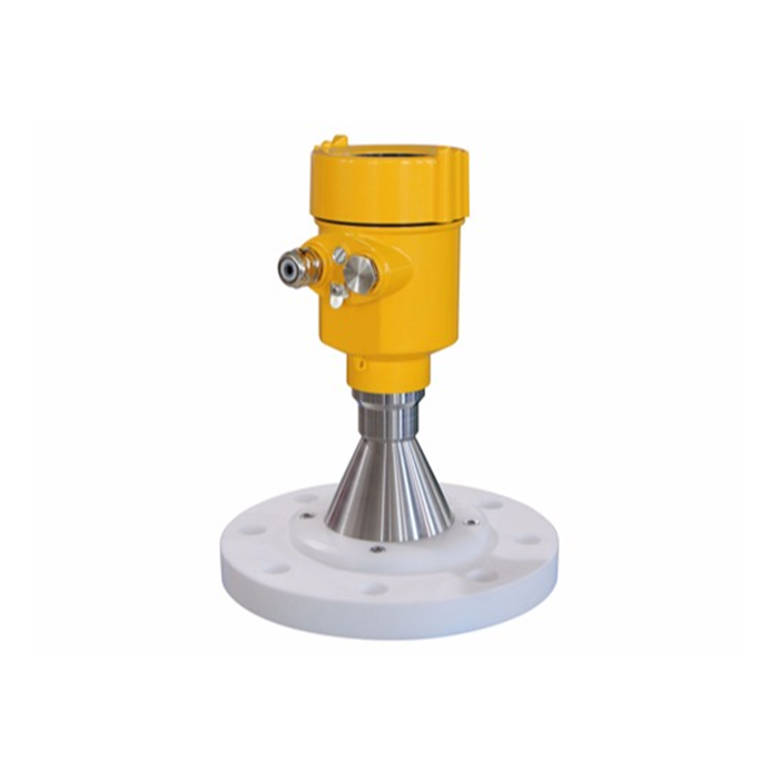
Horn Antenna
Horn antennas are mature industrial designs with good directivity and focusing. They are commonly used on liquid storage tanks, large process vessels, and some bulk solids applications. Corrosive media require additional attention to antenna material and process isolation.
Rod or Compact Process Antenna
Compact antennas are useful where process-connection space is limited. Confirm beam angle, nozzle size, nozzle length, material compatibility, condensation, and buildup conditions.
Flanged and Corrosion-Resistant Process Structures
High-temperature or corrosive service requires attention to flange standard, sealing material, antenna material, process isolation, temperature rating, and pressure rating.
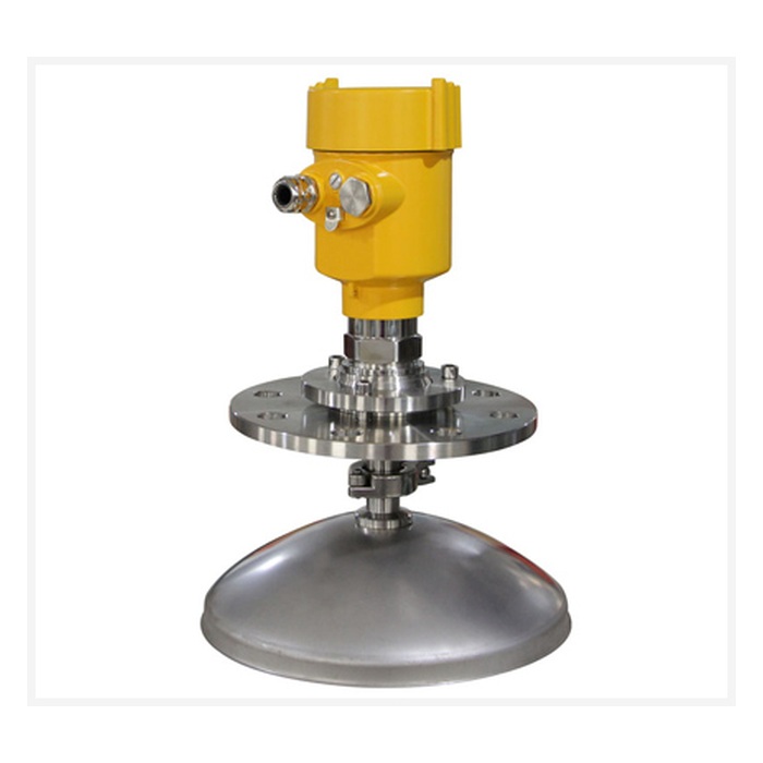
Parabolic or Large-Aperture Antenna
Some long-range or difficult bulk-solids applications benefit from stronger directivity and higher antenna gain. Selection should be based on silo height, dust, product surface, and required range.
How to Select for High Temperature, High Pressure, and Corrosive Media
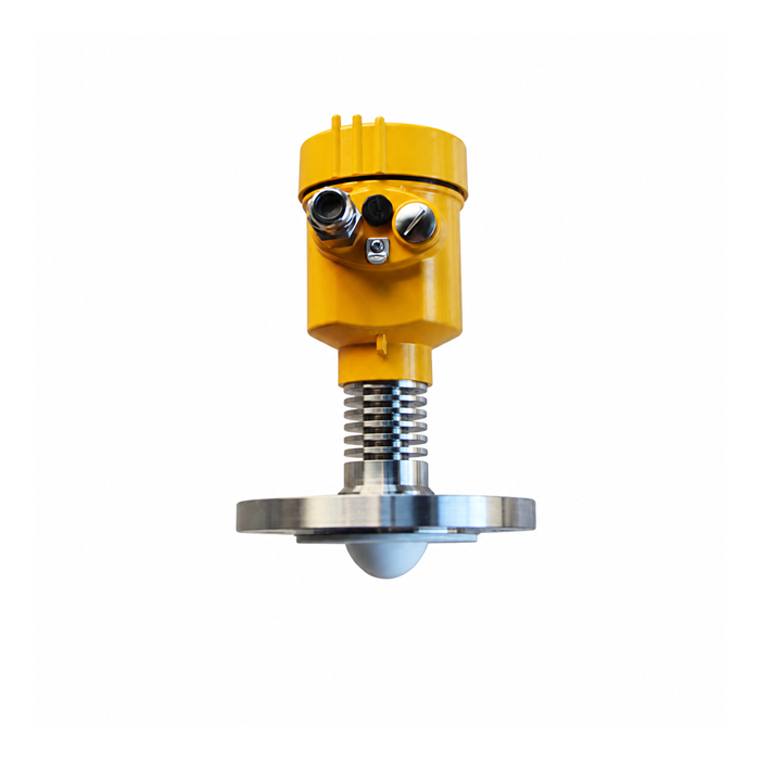
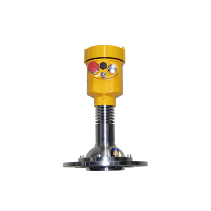
A high-temperature radar is not simply a standard radar with a stainless-steel housing. Real process-temperature capability depends on antenna design, flange, seals, process isolation, thermal extension, and electronics temperature limits.
For hot oil, residue oil, bitumen, or high-temperature chemicals, confirm both process temperature and ambient temperature. For pressurized vessels, confirm maximum working pressure, flange pressure class, sealing design, and required approvals.
Corrosive media may require PTFE, PEEK, stainless steel, or other compatible materials depending on the chemical composition.
How to Choose 4–20 mA, HART, or RS485
| Interface | Main Characteristics | Typical System |
|---|---|---|
| 4–20 mA | Mature analog signal with strong PLC/DCS compatibility | Radar → PLC AI |
| 4–20 mA/HART | Analog PV plus digital configuration and diagnostics | Radar → PLC / DCS / HART System |
| RS485 Modbus RTU | Digital data, multi-device bus, RTU/gateway friendly | Radar → RTU / Gateway → SCADA / IoT |
Not every radar level transmitter offers all three interfaces. Confirm the specific model configuration.
Correct Installation of Pulse Radar Level Transmitters
1. Do Not Install Directly Above the Filling Stream
The filling stream can create a strong dynamic echo and may be incorrectly detected as the product surface.
2. Avoid Strong Internal Reflectors
Limit switches, temperature probes, agitators, beams, coils, ladders, and internal structures can all create false echoes.
Do not apply one fixed rule, such as always using a set fraction of the tank diameter, to every radar installation. Instead, use the actual beam angle, vessel height, and internal geometry to determine a suitable mounting position.
3. Do Not Automatically Use the Center of a Domed Tank
Some domed roofs can create multiple reflections near the center. A suitable offset position should be selected according to vessel geometry and beam path.
4. Avoid Strong Vortex Zones
Strong agitation, rapid filling or emptying, and chemical reactions can create unstable surfaces. Consider installation position, damping, echo tracking, or, where appropriate, a stilling well or bypass arrangement.
5. Check Nozzle Geometry
Long, narrow metal nozzles may generate additional reflections. Confirm nozzle diameter, nozzle length, antenna size, and installation requirements for the specific model.
Where Do False Echoes Come From?
Common sources include tank walls, beams, pipes, ladders, agitators, heating coils, filling streams, nozzles, and antenna buildup.
A practical troubleshooting sequence is:
Optimize the mounting position.
Reduce strong structural reflections.
Configure vessel parameters correctly.
Perform false-echo mapping or interference suppression.
Set damping and echo tracking according to process dynamics.
Sealing, Condensation, and Antenna Buildup
Instrument Water Ingress
Check cable glands, seals, housing covers, cable entry direction, enclosure rating, and any required weather shield.
Antenna Condensation
Strong condensation can reduce useful echo quality. Depending on the application, consider installation position, insulation, anti-condensation design, or air purge.
Antenna Buildup
Viscous liquids, powders, or crystallizing products can accumulate on the antenna. Measurement impact depends on buildup thickness, dielectric properties, moisture content, coverage, and antenna design.
Cleaning methods must be compatible with the antenna, seals, and process materials. Do not use aggressive cleaning chemicals without first confirming material compatibility.
Typical METRAVON Industrial Applications
1. Chemical Storage Tanks
Site Challenge: Corrosive media, vapor, temperature, pressure, and complex internals.
Radar Level Transmitter → 4–20 mA/HART → PLC / DCS
User Value: Continuous non-contact level measurement for inventory, alarms, and process control.
2. High-Temperature Oil, Residue Oil, and Bitumen Tanks
Select the radar according to maximum process temperature, pressure, flange, antenna material, thermal isolation, and installation position.
3. Cement, Mineral Powder, Coal, and Ash Silos
Dust, angle of repose, wall buildup, and irregular bulk-solids surfaces require correct frequency, antenna, beam angle, and mounting position.
4. Reactors and Agitated Tanks
Use a suitable mounting position, antenna orientation, and false-echo mapping to avoid agitator shafts, coils, and other internal structures.
5. Multi-Tank Remote Level Monitoring
Radar Level Transmitters → RS485 Modbus RTU → RTU / Industrial Gateway → 4G / Ethernet → SCADA / IoT
What Should Be Confirmed Before Purchase?
| Selection Item | Required Information |
|---|---|
| Medium | Liquid, slurry, powder, granules, and exact product name |
| Range | Maximum distance from radar to the lowest product surface |
| Vessel Size | Height, diameter, and mounting position |
| Process Temperature | Normal and maximum temperature |
| Process Pressure | Normal and maximum pressure |
| Medium Properties | Corrosiveness, dielectric behavior, viscosity |
| Process Conditions | Foam, vapor, dust, agitation, condensation |
| Internals | Ladders, beams, coils, agitators, filling pipes |
| Process Connection | Thread, flange, and size |
| Output | 4–20 mA, HART, RS485 Modbus RTU |
| Environmental Protection | Outdoor, dust, water, corrosion |
| Hazardous Area | Required explosion-protection certification |
| Host System | PLC, DCS, RTU, SCADA, or industrial gateway |
How to Evaluate a Radar Level Supplier
1. Can the Supplier Select by Process Conditions?
The recommended model should be based on medium, range, temperature, pressure, vessel geometry, and process connection—not only the requested measurement distance.
2. Are Complete Technical Documents Available?
Request the datasheet, installation guide, operation manual, wiring diagram, outline dimensions, communication protocol, and Modbus register map where applicable.
3. Are Performance Claims Clearly Conditioned?
Statements such as “70 m range,” “±2 mm accuracy,” or “200 °C” should be tied to a specific model, antenna, process connection, medium, and defined conditions.
4. Can the Supplier Support System Integration?
For PLC, DCS, RTU, or gateway integration, confirm 4–20 mA scaling, HART availability, RS485 parameters, register mapping, power supply, and communication architecture.
5. Is Installation and Commissioning Support Available?
Many radar issues are caused by mounting position, range configuration, filling interference, false echoes, parameter settings, or antenna buildup rather than instrument failure.
FAQ
Q1: Is every 26 GHz radar a pulse radar?
No. 26 GHz describes the operating frequency. The specific signal-processing technology must be confirmed from the model datasheet.
Q2: Can radar measure corrosive liquids?
Yes, if the antenna, process connection, seals, and process-facing materials are compatible with the medium.
Q3: Is a high-temperature radar just a standard radar with a stainless-steel housing?
No. Temperature capability also depends on the antenna, process connection, seals, thermal isolation, and electronics limits.
Q4: Should radar always be mounted in the center of a tank?
No. Some vessel geometries create multiple reflections near the center. Mounting should be selected according to vessel geometry and beam path.
Q5: What happens if radar is mounted directly above the filling inlet?
The filling stream may create a strong dynamic echo and cause unstable or incorrect target detection.
Q6: Can radar still measure with dust or buildup on the antenna?
Light contamination may not immediately cause failure, but severe buildup, crystallization, or high-dielectric deposits can significantly affect the echo.
Q7: Can an RS485 radar connect directly to a cloud platform?
Normally an RTU or industrial gateway is required to convert RS485 Modbus RTU to MQTT, HTTP, TCP/IP, or another network protocol.
Q8: Is maximum range the only parameter that matters?
No. Medium, dielectric properties, blocking distance, beam angle, temperature, pressure, antenna, installation geometry, and communication interface are also critical.
Q9: Why does a radar level reading suddenly jump?
Common causes include false echoes, filling interference, agitation, weak true echo, antenna contamination, and incorrect configuration.
Q10: Is 80 GHz always better than 26 GHz?
No. 80 GHz often provides a narrower beam and better performance in complex vessel geometries, while the final choice still depends on medium, foam, vapor, condensation, range, and installation conditions.
Conclusion
Pulse radar is a mature non-contact level measurement technology. Stable performance depends on medium, dielectric properties, antenna, beam angle, temperature, pressure, vessel geometry, filling location, foam, vapor, condensation, false echoes, process connection, and communication interface.
METRAVON Radar Level Measurement Selection
For tanks, reactors, silos, and industrial level projects, provide the medium, liquid or solid state, maximum measurement distance, vessel dimensions, process temperature and pressure, foam, vapor, dust, agitation conditions, process connection, communication interface, PLC/DCS/RTU/gateway model, and site photos or drawings.
