


 Chinese
 Spanish
 Russian
 Portuguese
 French
 German
 Indonesian
 Thai
 Vietnamese
 Arabic
 Italian
 Turkish
 Polish
 Japanese


Radar level jumps during mixing can come from surface movement, a changing target or the way readings are sampled and displayed. A repeated pattern on a slow trend does not prove that the radar is detecting each passing blade. Compare instrument data with mixer operating states before increasing damping or changing the level offset.
Preserve the timing of the disturbance
Record mixer start, stop and speed changes alongside radar distance, status and the receiving-system value. Use available diagnostics from the supplied electronics; do not assume every output exposes a high-speed echo record. Establish how often each trace updates and whether the historian stores averages, selected samples or only changes above a threshold.
A periodic disturbance sampled too slowly can appear to have a different, slower period or can appear nearly constant. This is a sampling effect, not evidence of a new process cycle. A display refresh rate is therefore insufficient for identifying a mechanical frequency. Ask the integrator what data are actually stored before comparing a trend period with mixer speed.
Radar level jumps need a controlled comparison
| Observation | Useful comparison |
|---|---|
| At startup | Separate electrical switching time from the later development of surface motion. |
| At steady speed | Compare repeated disturbances using adequately timed instrument and process records. |
| At another speed | Check whether the behaviour changes under an authorised operating condition. |
| After stopping | Observe settling and recovery instead of comparing only the final quiet value. |
Any change to mixer operation must be approved by the process owner. Do not stop or vary equipment where doing so would create an unsafe or unacceptable process condition. Existing operating records may provide the needed comparison without a special test.
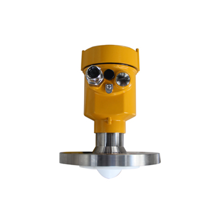
Inspect the measurement path once the evidence is organised
The METRAVON MV-RD12 lists an 8-degree beam angle. Plot the intended path against the shaft, blades, inlet and expected liquid levels. The possible interaction changes as the surface rises; a clear path at one level does not establish clearance throughout the batch.
If the local distance remains stable while only the PLC value jumps, investigate the receiving chain separately. If the local reading changes with mixing, review the actual target and available echo information. Distinguish a changing liquid surface from a competing reflection before altering suppression settings.
Filtering questions
Q1. Why not use enough damping to make the trend smooth?
Damping can reduce visible variation but also delay a real level change. First identify the disturbance and establish the response the process needs; then test the chosen filtering against both stability and detection delay.
Q2. Does a mixer-related pattern prove the sensor is faulty?
No. It may reflect real surface motion or an unsuitable viewing position. A replacement at the same location could behave similarly unless the measurement path and required quantity are addressed.
Summary
Use timed evidence to distinguish process motion, target changes and sampled-data effects. Send the mixer layout, operating states and unedited trends for an MV-RD12 troubleshooting review before changing filters.
