


 Chinese
 Spanish
 Russian
 Portuguese
 French
 German
 Indonesian
 Thai
 Vietnamese
 Arabic
 Italian
 Turkish
 Polish
 Japanese


Radar level meter surge protection must cover the electrical paths into the installation, not just the instrument enclosure. An outdoor transmitter may share a power supply with a cabinet, send a signal along a long cable and sit on a structure with its own bonding arrangement. Protecting one of those paths does not establish that the complete measurement system is protected.
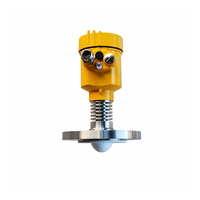
Draw the routes a disturbance can follow
Start with a site drawing showing the radar, field junction boxes, control cabinet, power source and connections between structures. Include supply and signal cables, not only the cable on which a previous failure was found. Nearby lightning and switching events can produce transient overvoltages without a direct strike on the sensor.
Record whether the route is exposed, crosses between buildings or enters a cabinet from outdoors. Give the drawing to the responsible electrical designer for the site risk assessment and protection design. Choosing a surge protective device, or SPD, is one part of that work; it does not replace the assessment of external lightning protection and bonding.
Radar level meter surge protection: match the circuit
A protector must suit both the electrical operating conditions and the signal it is expected to pass. A device selected for a power circuit should not be transferred to an RS485 pair merely because the nominal voltage sounds similar. Check the manufacturer's circuit designation and application data.
| Circuit | Check | Evidence |
|---|---|---|
| DC power | Operating voltage, current, permitted drop and coordinated protection requirements. | The instrument retains its required supply under the assessed operating conditions. |
| 4-20 mA | Loop arrangement, series resistance, leakage and the resulting voltage budget. | The complete analog path preserves the required scaling and fault behaviour. |
| HART | Compatibility of the protector and intervening equipment with the digital signal. | The required host can still communicate through the installed path. |
| RS485 | Signal circuit type, electrical loading and frequency characteristics. | Communication remains reliable at the specified network settings and topology. |
Keep the protector's maximum continuous operating voltage separate from its voltage protection level. The first concerns normal operation; the second describes protection under stated test conditions. Neither value alone proves suitability. The designer must compare the complete device data with the equipment and the installation, including how the protection stages work together.
For METRAVON MV-RD14, confirm whether the actual order uses a loop-powered analog arrangement or another electrical version. Do not assume that an accessory selected for one version suits another, or that an instrument's ingress-protection rating specifies its surge withstand capability.
Bonding and signal references are not interchangeable
Protective earth, functional bonding, cable shields, signal common and DC negative have different purposes. Their connections must follow the approved system drawings. Joining all of them together in the field is not a universal remedy for interference or surge exposure.
The physical routing of protection connections matters as well as their continuity. Rapid transient current can produce voltage along a connection that appears satisfactory in an ordinary resistance check. The installer should follow the specified connection layout and conductor requirements rather than add long loops to reach a convenient terminal.
Where a cable joins structures with different grounding conditions, have the whole link assessed. Protection at the transmitter alone may leave the cabinet input exposed. Electrical isolation or a suitable fibre link can be considered as part of a redesign, but neither removes the need to assess the remaining power and conductive paths.
Ask for a documented protection assembly
Provide the radar model and electrical version, cable route, receiving input, supply arrangement and site protection requirements. Request the relevant instrument electrical information for the project designer. Site lightning-protection design, accessory selection and installation approval must remain explicitly assigned rather than implied by the sensor purchase.
The supply scope should identify the protector, its circuit position, installation instructions and any status indication. Also identify who approves coordination with other protection equipment. Avoid a quotation that promises only "lightning protection included" without showing what is supplied and what site work remains necessary.
Hazardous-area installations need an additional compatibility review. An accessory may affect the approved protection concept or the electrical parameters of an intrinsically safe circuit. Do not infer compliance from the radar's certification alone. Obtain the applicable documents for the actual assembly and have them checked by the responsible specialist.
This review is not a field wiring procedure. Work on live circuits, process equipment and exposed structures must follow the site's electrical safety and access controls. Do not perform a field surge-injection test or an insulation-resistance test across connected electronics unless an approved procedure explicitly permits it.
Keep inspection separate from proof of protection performance
A visual inspection can identify damaged cable entries, corrosion, loose connections or a failed status indicator. A functional check can confirm that the radar and receiving system still operate. Neither recreates a surge test or proves the performance of an undocumented protection design.
After a disturbance, retain the event time, affected channels, supply alarms and protector condition before replacing parts. A working local display with a failed cabinet input points to a different investigation from repeated transmitter restarts. Follow the device instructions for assessment or replacement even when an external indicator appears normal.
Protection questions
Q1. Does a grounded metal tank make an SPD unnecessary?
Not by itself. Bonding the structure and limiting transient voltage on an incoming circuit address different parts of the installation. The requirement for additional protection must be assessed from the cable paths, site conditions and equipment, not from the tank material alone.
Q2. Is a protector with a higher discharge-current rating always better?
No single rating settles the choice. An unsuitable operating voltage or signal characteristic can cause problems even if the stated discharge capability is high. Require compatibility and coordination evidence for the circuit being protected.
Q3. Can an analog loop still work while HART communication fails?
Yes. Passing the current signal does not prove that the installed path passes the digital communication correctly. When HART is required, include a host communication check as well as an analog measurement check after installation.
Q4. Should shielding be connected at both ends?
There is no instruction that fits every installation. Follow the approved EMC, bonding and hazardous-area design for the selected equipment. Do not change shield connections to address one symptom without checking the effect on the rest of the circuit.
Summary
Assess the entire path from field instrument to cabinet, then select and install coordinated protection compatible with each circuit. Preserve normal measurement and communication while meeting the site's protection requirements. A grounded enclosure, a single component rating or a successful power-on check is not sufficient evidence on its own.
