


 Chinese
 Spanish
 Russian
 Portuguese
 French
 German
 Indonesian
 Thai
 Vietnamese
 Arabic
 Italian
 Turkish
 Polish
 Japanese



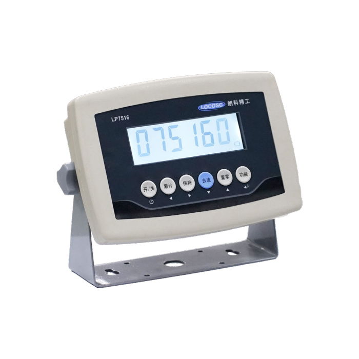
METRAVON MV-WI0007 is an economy weighing indicator for routine platform, bench and logistics-scale work. It uses a four-wire analogue sensor connection with 3.3 V excitation and a -7 to +12.8 mV input interval. The reference drive is one to four 350-ohm sensors. Its rechargeable-battery arrangement differs from an AA-powered indicator, so power, display and interface choices should be listed explicitly when comparing a replacement or new scale package.
Specify the economy weighing indicator around the daily task
List what the operator actually needs to see, enter and retain: a settled weight, a running accumulation, a check result or a printed record. Functions such as hold and animal weighing do not establish a particular moving-load accuracy or settling time. Ask for the operating sequence that will be supplied and try it with representative loads. A lower-cost instrument is useful only if its keys, display and record method support the intended workflow without requiring an unconfirmed accessory.
Check 3.3 V excitation against the existing sensor circuit
The input rating is a millivolt signal interval, not a tonne capacity assigned to the instrument. Obtain the sensor sensitivity, permitted excitation, resistance and actual wiring before reusing a platform. A bridge previously excited at 5 V may generate a different output at 3.3 V. Check the useful signal interval and tare offset with the chosen division rather than copying the old displayed capacity and assuming the electrical conditions are unchanged. Confirm any junction arrangement as part of that circuit.
| Item | Value | Selection notes |
|---|---|---|
| Sensor input / excitation | -7 to +12.8 mV / 3.3 V DC | Check sensor sensitivity and allowed excitation before retaining a platform. |
| Bridge connection / drive | Four-wire / one to four 350-ohm cells | The count does not describe independently sampled channels. |
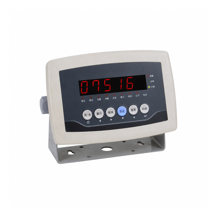
| Display alternatives | 20 mm LED / 25 mm LCD | Six digits; specify the actual enclosure and display version. |
| Display / internal counts | 15,000 / 1,000,000 | Verify the useful division; converter counts are not installed accuracy. |
| Internal battery reference | 4 V / 4 Ah | Rechargeable arrangement, not three AA dry cells. |
| Continuous-use reference | 50 hours with four 350-ohm sensors | Confirm battery, display and accessory conditions in the offer. |
Choose the rechargeable configuration and mains version
The reference internal battery is 4 V/4 Ah, with a 50-hour continuous-use figure stated for four 350-ohm sensors. Treat that as a specified reference condition and verify the supplied battery, display and accessories before using it for operational planning. The mains descriptions use 110/220 V or a stated interval ending at 220 V; obtain the actual input rating and selection requirements. Do not substitute a battery or charger from another indicator solely because the enclosure looks similar.
Separate the required serial interface from option symbols
RS232 and a shared serial-printer connection are described, with selectable 600-9600 baud. BLE and other wireless or RS485 option symbols also appear, but they are not a wiring schedule for every unit. Specify which connection is required, whether printing and data collection must run together, and what receiving device will be used. Obtain the fitted interface and message description. Do not infer Modbus RTU from an RS485 symbol or assume that a Bluetooth version works with an arbitrary application.
Set a useful division and keep the replacement record
The references list 15,000 display counts, 1,000,000 internal counts and a 1 microvolt-per-verification-interval minimum signal. They do not make the completed scale accurate to every displayed digit. Verify the selected division through an agreed calibration and repeated loading procedure with the actual platform and connections. Check tare, unloading return, accumulation or hold behaviour and any output record that the task uses. Record the display type, battery, mains version, input wiring and interface configuration alongside the calibration settings.
Battery configuration and routine operation
Q1. Is this interchangeable with a three-AA-cell indicator?
The battery and supply arrangements differ. Compare the actual bridge excitation, input interval, wiring, mounting and calibration procedure as well as the power source before approving a replacement.
Q2. Does the RS485 option symbol prove Modbus support?
No protocol is established by that symbol alone. Request the actual serial option and its documented message or command format for the receiver you intend to use.
Q3. Is the 50-hour reference valid with any display and radio option?
The stated reference includes four 350-ohm sensors but does not approve every accessory combination. Obtain the duty statement for the supplied configuration and allow practical power reserve.
Q4. What should be tested before selecting the hold function?
Confirm when the value is captured, how it is released and how the operator distinguishes a held result from a live reading. Check the intended moving or unstable load under the agreed operating procedure, not just a stationary display.
