


 Chinese
 Spanish
 Russian
 Portuguese
 French
 German
 Indonesian
 Thai
 Vietnamese
 Arabic
 Italian
 Turkish
 Polish
 Japanese


Radar level measurement in agitated tanks has two separate difficulties: the radar can select the wrong reflector, or it can correctly measure a surface that no longer represents the required tank level. More damping cannot resolve that distinction.
Decide Which Operating Value the Process Needs
For mixing control, the required value may be a responsive indication while the agitator runs. For batch reconciliation, a settled surface may give a more meaningful reference. Identify the intended use before selecting the mounting point or agreeing an error limit. A local vortex depth is not automatically the average level used by a tank-volume calculation.
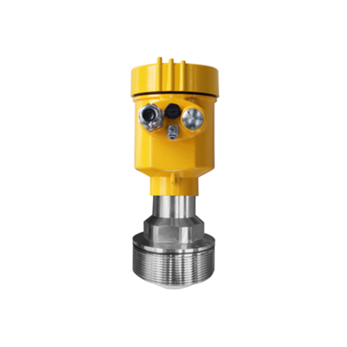
The MV-RD13 offers a listed 3-degree beam with a 76 mm PTFE antenna. That can help separate a liquid surface from internals, provided the process connection and available position suit the antenna. It does not establish measurement through every foam layer or at every mixer speed.
Plan Radar Level Measurement in Agitated Tanks by Operating State
| State | Observe | Meaning |
|---|---|---|
| Stopped | Settled reference level and fixed internal echoes. | Establish the geometry before assessing moving disturbances. |
| Running | Selected echo, speed, vortex and output response. | Separate blade selection from a genuine change in local surface height. |
| Filling | Inlet stream, splash, foam and simultaneous mixing. | Check the combined disturbance rather than testing each in isolation. |
| Draining | Blade exposure and low-level echo behaviour. | Identify where the useful liquid echo becomes difficult to distinguish. |
Use the Swept Blade Envelope, Not a Stopped Photograph
Plot the shaft, complete blade travel, baffles and inlet on the plan and elevation. A blade can cross the measurement path periodically even though the stopped machine looks clear. Review the beam footprint at blade height and at the lowest measured surface.
Avoid direct filling impact and provide access to inspect deposits. Moving toward the wall may avoid the shaft but introduce a baffle, wall reflection or rising surface region. Choose a position from the actual vessel geometry rather than prescribing a universal fraction of tank radius.
Tune Response Only After Target Selection Is Correct
Compare diagnostic curves with the mixer stopped and at the required operating speeds. If the instrument follows a blade, investigate placement and echo selection before increasing averaging. False-echo mapping of a broad region can suppress a real liquid surface as it moves through the same distance.
Once the target is credible, select damping from the permitted delay in the process response. Verify filling alarms with that setting active. A smooth trend that misses a rapid rise is unsuitable for that duty even if it looks better on the operator display.
Mixing-Service Questions
Q1. Must the agitator stop for every reading?
Not necessarily. Demonstrate operation at the required speeds and levels. If only settled measurements can meet the inventory requirement, identify that limitation explicitly and use a defined settling procedure.
Q2. Will an empty-vessel echo map remove blade interference?
It cannot be assumed to describe a rotating and partly submerged blade. Preserve diagnostic evidence for both conditions and avoid treating every intermittent return as a fixed obstacle.
Summary
Confirm what the observed surface means, then prove echo selection under actual mixing conditions. Request an agitated-vessel installation review with blade dimensions, operating speeds and the intended control or inventory duty.
