


 Chinese
 Spanish
 Russian
 Portuguese
 French
 German
 Indonesian
 Thai
Thai Vietnamese
 Arabic
 Italian
 Turkish
 Polish
 Japanese

What Is the HART Protocol?
HART stands for Highway Addressable Remote Transducer. It is a bidirectional digital communication protocol designed for industrial process instrumentation.
Its most important characteristic is:
Digital communication is superimposed on a traditional 4–20 mA analog current loop.
As a result, a smart transmitter that supports HART can provide two types of information at the same time.
4–20 mA Analog Signal
The analog signal is used to continuously transmit the main process variable, such as:
Pressure;
Level;
Temperature;
Flow;
Differential pressure.
HART Digital Communication
At the same time, HART digital communication can be used to read additional information such as:
Primary Variable, PV;
Secondary, tertiary, and quaternary variables;
Instrument range;
Engineering units;
Device Tag;
Device status;
Diagnostic information;
Calibration parameters;
Sensor status;
Fault information.
This makes HART particularly suitable for industrial plants that already use large numbers of 4–20 mA field instruments.
HART does not require an existing analog system to be completely replaced in order to add digital communication. Instead, it adds digital information to the existing current loop.
The core concept of HART is therefore to allow the traditional 4–20 mA process signal and digital device information to coexist on the same field wiring.
How Does the HART Protocol Work?
The classic wired HART communication method uses FSK, Frequency Shift Keying.
It is based on Bell 202 FSK technology and superimposes two AC frequencies on top of the 4–20 mA DC current signal.
The main parameters are:
| Parameter | Typical HART FSK Characteristic |
|---|---|
| Analog Process Signal | 4–20 mA |
| Digital Modulation | FSK, Frequency Shift Keying |
| Logic 1 | 1200Hz |
| Logic 0 | 2200Hz |
| Communication Speed | 1200bit/s |
| Digital Signal Amplitude | Approximately 1 mA peak-to-peak, or about ±0.5 mA |
| Communication Type | Bidirectional, half-duplex |
| Physical Layer Basis | Bell 202 FSK |
| Typical Topologies | Point-to-point and multidrop |
| Data Exchange | Request-Reply, with optional Burst Mode |
The HART FSK digital signal is an AC signal with an average value of approximately zero. Under normal loop design conditions, it therefore does not change the original 4–20 mA DC process signal.
HART can therefore be understood as two communication channels operating on one 4–20 mA current loop:
Analog channel: 4–20 mA → Transmits the main process variable
Digital channel: HART FSK → Transmits configuration, status, diagnostics, and additional process information
Why Does HART Communication Not Affect the 4–20 mA Signal?
This is one of the key concepts for understanding HART.
For example, assume a pressure transmitter is currently outputting:
12 mA
The PLC reads the 12 mA signal through its analog input module and converts it into a pressure value.
At the same time, the HART transmitter superimposes a small AC FSK communication signal on top of the 12 mA DC current.
Because the average value of the digital FSK signal is approximately zero, the PLC still sees an average DC current of about:
12 mA
Therefore:
The PLC continues to read the 4–20 mA process variable
while:
A HART handheld communicator, HART modem, or HART-capable I/O module can read the digital information at the same time.
This is one of the main reasons HART can coexist with traditional 4–20 mA systems.
Which Communication Layers Does HART Use?
The HART protocol can be related to several layers of the OSI model.
Physical Layer
The physical layer defines:
Electrical signaling;
FSK frequencies;
Signal amplitude;
Transmission wiring;
Loop impedance;
Connection requirements.
Classic wired HART uses Bell 202 FSK technology.
Data Link Layer
The data link layer is responsible for:
Frame structure;
Device addressing;
Host access;
Error checking;
Request and response timing.
HART uses asynchronous communication. In the classic 1200 Baud FSK network, each character contains:
1 start bit + 8 data bits + 1 odd parity bit + 1 stop bit
This gives a total of:
11 bits per character
Application Layer
The application layer defines what information is actually exchanged between the host and the field instrument.
Typical functions include:
Reading the primary variable;
Reading device information;
Reading the configured range;
Changing parameters;
Reading diagnostic status;
Executing device operations.
HART defines a standardized command structure so that host systems and field devices can communicate in a consistent way.
What Types of HART Commands Are Available?
From an engineering perspective, HART commands can be divided into three main categories.
Universal Commands
All devices compliant with the applicable HART specification must support the required Universal Commands.
These commands can be used to read information such as:
Device identification;
Primary Variable;
Device status;
Dynamic variables.
This category has the highest degree of standardization and provides the basis for basic interoperability between different devices and host systems.
Common Practice Commands
Common Practice Commands provide frequently required device functions, although not every instrument must support every command.
Typical examples include:
Setting parameters;
Adjusting range;
Reading additional device information;
Performing instrument maintenance functions.
The actual supported commands depend on the capabilities of the specific instrument.
Device-Specific Commands
Manufacturers can implement device-specific commands to provide functions that are unique to particular instruments.
For example, a smart radar level transmitter, pressure transmitter, or multivariable instrument may support:
Special echo parameters;
Sensor diagnostics;
Special calibration functions;
Advanced configuration parameters.
Therefore, the statement “supports HART” does not mean that every HART instrument provides exactly the same advanced functions.
HART Point-to-Point Communication
Point-to-point communication is the most common HART configuration in industrial field applications.
A typical architecture is:
24 VDC power supply → HART smart transmitter → 4–20 mA loop → PLC / DCS
A HART handheld communicator or HART modem can also be connected to the loop.
In this mode, the 4–20 mA signal is still used to transmit the main process variable.
For example, a radar level transmitter may be configured as:
4 mA = 0m
20 mA = 10m
The PLC can read the liquid level directly from the 4–20 mA signal.
At the same time, maintenance personnel can use HART communication to read:
Real-time level;
Distance;
Device Tag;
Measurement range;
Device status;
Diagnostic information;
Configuration parameters.
The key characteristic of point-to-point HART is therefore:
The analog signal provides the fast, continuous primary process value, while digital HART communication provides additional device information.
What Is HART Multidrop Communication?
HART also supports multidrop communication.
In this architecture, multiple HART instruments can be connected to the same pair of communication wires and addressed using different Polling Addresses.
A simplified topology is:
HART Host
   |
Two-Wire Bus
   |
   +-- HART Device 01
   +-- HART Device 02
   +-- HART Device 03
   +-- HART Device ...
A common statement found in older technical documents is:
HART can connect a maximum of 15 instruments.
This statement does not apply to every HART protocol version.
The multidrop capability differs by version:
HART 5: up to 15 field devices
HART 7: up to 62 field devices
HART 7 uses a larger polling-address space, so 15 instruments should not be treated as a universal limit for all modern HART systems.
In classic multidrop mode, process variables are primarily read digitally. The loop current of each field device is normally fixed near its minimum value, typically around 4 mA, instead of using the changing 4–20 mA current to represent the primary process value.
Multidrop HART is therefore useful for certain applications, but point-to-point architecture with one 4–20 mA loop per instrument remains very common in conventional PLC and process-control systems.
HART Request-Reply and Burst Mode
The basic HART communication mechanism is:
Request → Reply
The process is:
The host sends a command;
The field instrument receives the command;
The instrument returns the requested data.
For example:
PLC / HART host → Read PV
The instrument may respond:
PV = 6.25m
This communication structure is easy to manage and helps prevent multiple devices from transmitting at the same time.
HART also supports optional Burst Mode.
In Burst Mode, after the host has configured the device, the field instrument can continuously publish selected data without waiting for a normal polling request every time.
Why Does a HART System Often Use a 250-Ohm Resistor?
This is one of the most common questions during HART commissioning.
A HART modem or handheld communicator must detect the AC FSK signal in the current loop.
If the AC impedance of the entire loop is too low, the voltage generated by the HART signal may be too small for reliable communication.
The result may be:
4–20 mA works normally, but HART communication cannot be established.
For this reason, approximately:
250Ω load resistance
is commonly used during HART commissioning.
A typical test loop is:
24 VDC → HART transmitter → 250Ω resistor → Power loop
The HART modem is usually connected in parallel across an appropriate HART signal measurement point.
However, it is important to understand that:
Not every HART system requires an additional external 250Ω resistor.
The PLC analog input module, isolator, barrier, or other loop device may already provide sufficient resistance.
The total loop impedance should therefore be calculated and checked before adding another resistor.
Why Does 4–20 mA Work While HART Communication Fails?
This is a common field troubleshooting situation.
1. Insufficient Loop Impedance
For example:
24 VDC + 2-wire transmitter
may operate correctly as a 4–20 mA loop but fail to provide enough HART signal voltage if there is insufficient load resistance.
The result is that the HART modem cannot detect a strong enough FSK signal.
2. Signal Isolator Does Not Support HART Pass-Through
Some older signal isolators can transmit the DC 4–20 mA signal correctly but cannot pass the AC frequencies used by HART.
3. Safety Barrier or Intrinsically Safe Equipment Is Not HART Compatible
In hazardous-area applications, safety barriers and isolators must be checked for HART compatibility.
4. Excessive Cable Capacitance
Very long cables or unsuitable cable types may attenuate the higher-frequency HART signal.
5. Incorrect Wiring
The HART modem should be connected according to the instrument instructions, normally in parallel at the appropriate point, rather than inserted arbitrarily in series with the loop.
6. The Instrument Does Not Support or Enable HART
During procurement, it is important to confirm that:
4–20 mA
and:
4–20 mA + HART
are not necessarily the same output configuration.
What Are the Advantages of the HART Protocol?
1. Compatibility with Existing 4–20 mA Systems
This is one of HART's most important engineering advantages.
Large numbers of PLC and DCS installations already use 4–20 mA analog inputs.
If the field instrument also supports HART, the existing analog control architecture can be retained while digital communication is added.
Therefore, an industrial plant does not necessarily need to redesign the complete field wiring system just to obtain smart-device information.
2. Analog and Digital Information on the Same Pair of Wires
A conventional 4–20 mA transmitter mainly tells the control system:
What is the current measured value?
HART can additionally provide information such as:
Which instrument is connected;
What measurement range is configured;
What engineering unit is being used;
Whether an alarm is active;
What the sensor status is;
Whether maintenance may be required;
What additional variables are available.
This significantly increases the amount of information available from an intelligent field instrument.
3. Supports Remote Configuration
Maintenance personnel may be able to configure certain parameters through a HART handheld communicator or software without opening the instrument enclosure.
Typical functions include:
Setting measurement range;
Changing the Tag;
Changing engineering units;
Reading process variables;
Checking diagnostic information.
This can reduce field maintenance work in plants with large numbers of instruments.
4. Supports Device Diagnostics
HART digital communication can provide more device-status information than a simple 4–20 mA signal.
Depending on the instrument, this may include:
Sensor faults;
Device status;
Output status;
Configuration changes;
Diagnostic information.
This information can support preventive maintenance and fault diagnosis.
5. High Degree of Standardization
HART defines standardized communication mechanisms and Universal Commands.
Compliant instruments must correctly implement the applicable universal commands, which provides a basis for basic interoperability between field devices and host systems.
What Are the Disadvantages of the HART Protocol?
HART is not the ideal communication method for every industrial application.
1. Relatively Low Digital Communication Speed
Classic HART FSK communication operates at:
1200bit/s
This is suitable for:
Instrument configuration;
Device diagnostics;
Slow process data;
Maintenance information.
However, it is not suitable for:
Large volumes of high-speed data;
High-frequency sampling;
Images;
Large files;
High-speed motion control.
This is one of the clearest differences between classic HART and modern high-speed industrial Ethernet systems.
2. Limited Efficiency for Large-Scale Multi-Parameter Data Acquisition
Although HART can connect multiple devices, the 1200bit/s bus bandwidth can become a limitation if many instruments must be polled frequently for multiple digital variables.
Therefore:
The ability to connect many devices does not mean that the network is suitable for high-frequency acquisition from many devices.
3. Requires Attention to Loop Impedance and Device Compatibility
A basic 4–20 mA loop is relatively straightforward when power supply, load, and measurement range are correct.
When HART is added, additional factors must be considered:
HART impedance;
Cable capacitance;
Safety barriers;
Signal isolators;
Analog input modules;
HART modems;
Wiring topology.
Some devices can transmit 4–20 mA correctly but may not pass HART communication.
4. Advanced Functions May Require Device Description Files
If only standard Universal Commands are required, compatibility is relatively simple.
However, if the host needs access to:
Advanced parameters;
Manufacturer-specific diagnostics;
Special configuration functions;
the system may require:
EDD / DD / FDI Device Package
This makes system integration more complex than simply reading a 4–20 mA signal.
What Is the Difference Between HART and RS485 Modbus RTU?
This is a common question when selecting industrial sensors and transmitters.
| Item | 4–20 mA + HART | RS485 Modbus RTU |
|---|---|---|
| Basic Signal | 4–20 mA analog + digital FSK | Fully digital communication |
| Physical Interface | Current loop | RS485 differential bus |
| Typical Communication Speed | 1200bps | Commonly 9600bps, 19200bps, and others |
| Analog Output | Yes | Normally no |
| Digital Parameter Reading | Supported | Supported |
| Multi-Device Bus | Supported | Supported |
| Compatibility with Traditional PLC Systems | Very strong | Requires an RS485 interface |
| Primary Analog Variable if Digital Communication Fails | 4–20 mA may continue transmitting the PV | Depends on digital communication |
| IoT Gateway Integration | Possible if the gateway supports HART | Very common |
| Typical Applications | Process industry, DCS, smart transmitters | PLC, RTU, IoT, industrial data acquisition |
Neither protocol is universally better. The correct choice depends on the control and communication architecture.
When Should HART Be Selected?
If the existing system already uses:
4–20 mA + PLC / DCS
but the project also requires:
Parameter reading;
Remote configuration;
Status diagnostics;
Device management;
then:
4–20 mA + HART is often a suitable choice.
For example:
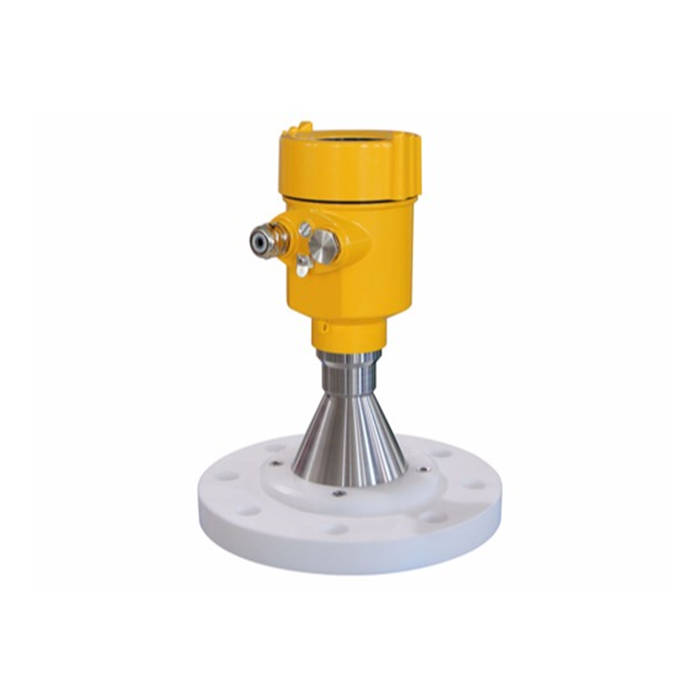
Radar level transmitter → 4–20 mA/HART → PLC / DCS
Even if digital HART communication is not used immediately, the PLC can still obtain the primary level value from the 4–20 mA signal.
When Should RS485 Modbus RTU Be Selected?
If the system focuses on:
Multiple sensor integration;
Digital data acquisition;
RTU communication;
4G gateways;
MQTT;
HTTP;
IoT cloud platforms;
then RS485 Modbus RTU is often more direct.
A typical architecture is:
Sensor → RS485 Modbus RTU → IoT gateway → 4G / Ethernet → MQTT / HTTP → Cloud platform
Modbus RTU is therefore common in remote water-level monitoring, agricultural monitoring, environmental monitoring, and industrial IoT systems.
Which Industrial Instruments Commonly Use HART?
HART is widely used in process automation instruments.
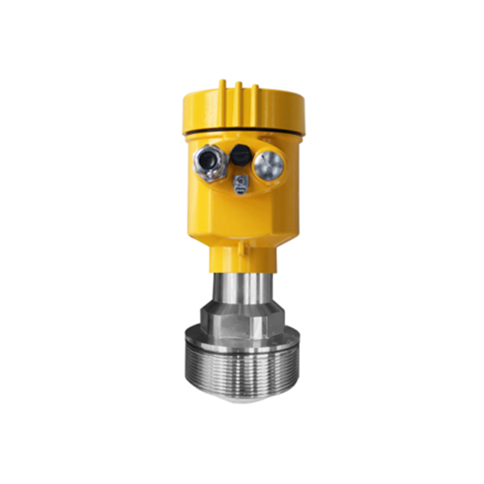
Radar Level Transmitters
Typical architecture:
Radar level transmitter → 4–20 mA/HART → PLC / DCS
The system can simultaneously obtain the analog level signal and digital device information.
Pressure Transmitters
The pressure value is transmitted to the PLC through 4–20 mA, while HART can be used for range configuration, status reading, and maintenance.
Differential Pressure Transmitters
Common applications include:
Flow measurement;
Filter differential pressure;
Process pressure.
Temperature Transmitters
RTDs or thermocouples can be connected to a temperature transmitter that converts the sensor signal into 4–20 mA/HART for connection to the control system.
Flow Meters
Some flow instruments use HART for:
Process variable reading;
Unit configuration;
Diagnostics;
Parameter management.
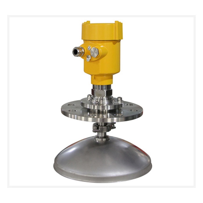
How Can METRAVON Industrial Instruments Be Integrated into a HART System?
For METRAVON industrial instrumentation projects, if a specific instrument model supports 4–20 mA/HART output, the communication architecture can be designed according to the existing control system.
For example:
Field Instrument
      |
4–20 mA / HART
      |
  PLC / DCS
The system can also include:
HART handheld communicator / HART modem / HART I/O
If the project needs to upload device data to an industrial Internet or remote monitoring platform, the architecture can be:
HART instrument → HART gateway or HART-capable data acquisition device → Ethernet / 4G → SCADA or IoT platform
Important:
Not every METRAVON industrial instrument supports HART by default.
The required output should be confirmed according to the specific model:
4–20 mA;
4–20 mA/HART;
RS485 Modbus RTU.
What Should Be Confirmed When Integrating a HART System?
When purchasing or integrating a HART instrument, the following parameters should be confirmed:
HART protocol version;
2-wire or 4-wire configuration;
Power supply voltage range;
4–20 mA measurement scaling;
Maximum allowable loop resistance;
Whether the PLC analog input module supports HART;
Whether a safety barrier or signal isolator is installed;
Whether the isolator supports HART pass-through;
Whether a HART handheld communicator is required;
Whether a PC HART modem is required;
Whether DD, EDD, or FDI device files are required;
Whether manufacturer-specific parameters need to be read.
For hazardous-area applications, intrinsic safety parameters, safety barriers, power supply, and the complete loop design must also be considered. The communication protocol alone is not sufficient for system design.
FAQ: Common Questions About the HART Protocol
Q1: Is HART an Analog or Digital Signal?
It includes both.
Classic HART superimposes digital FSK communication on the 4–20 mA analog signal, allowing analog process information and digital device data to coexist on the same loop.
Q2: What Is the HART Communication Speed?
Classic wired HART FSK communication operates at:
1200bit/s
This is suitable for instrument configuration, diagnostics, and process data reading, but not for high-speed data communication.
Q3: Does HART Require RS485?
No.
Classic wired HART uses FSK communication on a 4–20 mA current loop, while RS485 is a differential serial physical interface.
They are different physical communication technologies.
Q4: What Is the Relationship Between HART and 4–20 mA?
4–20 mA transmits the primary process variable.
HART adds digital communication to the same loop.
Therefore:
4–20 mA/HART is not the same as simple 4–20 mA.
Q5: Why Is a 250-Ohm Resistor Commonly Used for HART Communication?
A HART modem requires sufficient AC signal voltage for reliable communication.
A 250Ω load is a common engineering configuration.
If the PLC input module or another device already provides sufficient loop resistance, an additional resistor may not be necessary.
Q6: How Many Devices Can Be Connected in a HART Multidrop Network?
The answer is not always “15 devices.”
The number depends on the HART version:
HART 5: up to 15 devices
HART 7: up to 62 field devices
The actual system capacity also depends on power supply, current consumption, communication bandwidth, network topology, and device compatibility.
Q7: Can a HART Transmitter Connect to a Normal PLC Analog Input?
The 4–20 mA part usually can.
However, if the PLC also needs to read HART digital information, the PLC analog input module or an external communication device must support HART.
Q8: Can a Normal 4–20 mA Sensor Be Converted to HART by Software?
No, not by software alone.
HART requires appropriate physical-layer modulation and demodulation hardware, a HART protocol stack, and a compliant device implementation.
Q9: Which Is Better for Industrial IoT, HART or Modbus?
If the main architecture is:
RS485 sensor → Gateway → 4G → MQTT / HTTP
Modbus RTU is usually more direct.
If the existing industrial system is based on:
4–20 mA → PLC / DCS
and additional configuration, diagnostics, and device information are required, HART may be more suitable.
Q10: If HART Communication Fails, Will the 4–20 mA Signal Also Stop Working?
Not necessarily.
One of the key characteristics of HART is that digital communication and the 4–20 mA primary process signal can coexist.
For example, if HART communication fails because of modem problems, insufficient loop resistance, or compatibility issues, the 4–20 mA process signal may still continue to operate normally.
This is an important engineering advantage of HART in conventional process automation systems.
Conclusion: The Core Value of HART Is Digital Communication While Retaining 4–20 mA Compatibility
The HART protocol was not designed primarily for high-speed communication.
Its main value is:
To retain the mature and reliable 4–20 mA analog process signal while adding bidirectional digital communication over the same field wiring.
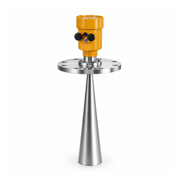
As a result, a HART-enabled pressure transmitter, radar level transmitter, temperature transmitter, or flow instrument can provide the primary process variable to the PLC while also providing configuration, status, and diagnostic information to maintenance and asset-management systems.
From a system-selection perspective:
For traditional process control, PLC/DCS applications, and upgrades of existing 4–20 mA systems, 4–20 mA/HART is often worth considering.
For multi-sensor digital acquisition, RTUs, 4G gateways, and industrial IoT projects, RS485 Modbus RTU may provide a more direct integration path.
For METRAVON industrial instrumentation projects, the PLC/DCS interface, transmission distance, number of instruments, diagnostic requirements, IoT platform requirements, and reuse of existing 4–20 mA field wiring should be confirmed before selecting 4–20 mA, 4–20 mA/HART, or RS485 Modbus RTU.
