


 Chinese
 Spanish
 Russian
 Portuguese
 French
 German
 Indonesian
 Thai
Thai Vietnamese
 Arabic
 Italian
 Turkish
 Polish
 Japanese

I. What Is an FMCW Radar Level Gauge?
A frequency-modulated continuous-wave radar level instrument is commonly referred to as an FMCW radar level instrument.
Its basic operating principle is to continuously vary the radar transmission frequency within a certain frequency range and receive the signal reflected from the surface of the measured medium. The instrument analyzes the frequency difference between the transmitted signal and the echo signal to calculate the distance from the radar to the surface of the medium, and then converts the distance into liquid level or material level.
Some 24 GHz FMCW radar instruments use a linear sweep bandwidth of approximately 1 GHz and perform periodic scanning through the antenna. Operating frequencies and sweep bandwidths vary between different models, and the actual parameters should be based on the specific product datasheet.
II. What Are the Features of FMCW Radar Level Gauges?
1. Continuous Frequency-Sweep Measurement
FMCW radar measures distance through continuous linear frequency sweeping.
Unlike systems that rely solely on a fixed-frequency signal, frequency-modulated continuous-wave radar determines the target position according to the frequency difference between the transmitted signal and the returned echo, making it suitable for continuous liquid level and material level monitoring.
2. Suitable for Various Solid Materials
FMCW radar level instruments can be used for various bulk solids and industrial raw materials, including:
Coal;
Cement;
Grain;
Alumina;
Limestone;
Chemical raw materials.
In industries such as cement, chemicals, environmental protection, power generation, and food processing, radar measurement can be used for continuous level monitoring in silos and storage tanks.
3. Non-Contact Measurement
Free-space radar measures the distance to the material surface using electromagnetic waves and generally does not require measuring components to come into direct contact with the medium.
For powders, granular materials, and certain corrosive media, this can reduce wear and maintenance problems caused by direct contact between mechanical measuring components and the medium.
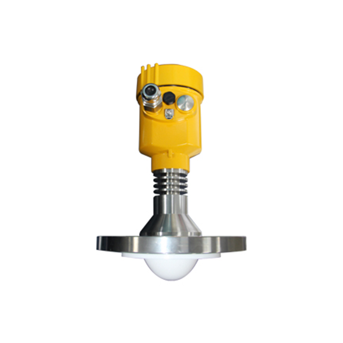
III. Main Advantages of FMCW Radar Level Instruments
The application range of FMCW radar level instruments depends on radar frequency, antenna type, signal-processing capability, and actual operating conditions.
Under suitable operating conditions, the main features include:
Continuous non-contact measurement;
Suitable for liquids or solid materials;
Suitable for relatively long-distance level measurement;
Different antennas can be configured according to operating conditions;
Can be used in industrial environments involving dust, steam, or complex media;
Suitable for storage tanks, silos, and process vessels.
Actual performance should be evaluated according to the specific model, medium, and installation conditions.
IV. What Types of Antennas Are Available for Radar Level Gauges?
Radar level gauges can be equipped with different antenna types according to application conditions, including:
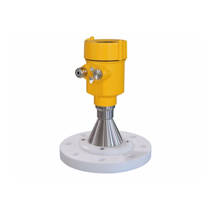
Horn antennas;
Parabolic antennas;
Array antennas;
Rod antennas;
Drop-shaped antennas;
Planar antennas;
Hygienic designs.
Different antennas vary in beam angle, installation dimensions, corrosion resistance, adaptability to material buildup, and process connections.
Therefore, antenna selection should be matched to the medium and site operating conditions rather than determined solely by the measurement range.
V. How Should a Radar Level Gauge Model Be Selected?
When selecting a radar level gauge model, the actual measurement environment should be carefully evaluated.
The following operating conditions should be confirmed:
Whether corrosive volatile gases are present above the medium;
Whether large amounts of water vapor are present;
Whether large amounts of dust are present;
Whether the medium is prone to crystallization;
Whether a large amount of foam is present on the liquid surface;
Whether the liquid surface fluctuates significantly;
Whether the measured material is powder or granular material;
Whether the liquid is highly corrosive;
Whether the medium has high viscosity.
In addition, the following should also be confirmed:
Maximum measurement distance;
Process temperature;
Process pressure;
Installation connection;
Antenna type.
Measurement range is only one parameter in radar selection and should not be used as the sole basis for selecting a model.
VI. What Should Be Considered When Installing a Guided Wave Radar Level Gauge?
Guided wave radar uses a probe rod or steel cable to guide the radar signal. Therefore, in addition to electrical installation, the mechanical position of the guided wave element must also be considered.
1. Disconnect Power Before Replacing the Instrument
Before removing the original level gauge or carrying out wiring work, disconnect the instrument power supply and handle the signal wiring in accordance with on-site electrical safety regulations.
Restore power only after installation and wiring have been completed and checked.
2. Avoid Inlets and Areas with Strong Disturbance
Guided wave radar should not be installed directly at water inlets, feed inlets, or locations where the liquid surface fluctuates violently.
Incoming liquid or material may impact the probe rod or steel cable and cause measurement fluctuations.
During installation, the guided wave element should also be prevented from directly contacting the following structures:
Pool walls;
Tank walls;
Supports;
Pipes;
Other metal structures.
3. Maintain Reasonable Clearance Around the Probe Rod or Steel Cable
If the guided wave steel cable contacts a metal wall, additional reflections may occur and mechanical wear may also develop over time.
Therefore, the guided wave element should be positioned properly during installation, with the necessary clearance maintained according to the actual vessel structure.
The specific installation distance should be determined according to the instrument manual and the actual site structure.
VII. How Should Cable Waterproofing Be Handled for Outdoor Guided Wave Radar?
In outdoor or humid environments, the cable entry is one of the areas requiring particular protection.
The following points should be considered during cable installation:
Securely tighten the cable gland;
Seal conduit connections properly;
Maintain the waterproof integrity of the instrument enclosure;
Ground shielded cables correctly;
Provide a drip loop before the cable enters the instrument.
A drip loop means allowing the cable to form a downward bend before it enters the instrument.
This allows rainwater or condensation to drip from the lowest point, reducing the risk of water traveling along the cable into the instrument enclosure.
VIII. What Should Be Considered During Signal Cable Insulation Testing?
Some industrial installation projects require insulation testing after signal cables have been installed.
For example, certain project specifications may require:
500 VDC test voltage;
60 s test duration;
Insulation resistance ≥20 MΩ.
These are specific project acceptance requirements and are not universal parameters for all radar level gauge projects.
Before performing an insulation test, confirm that the instrument electronics have been disconnected from the circuit. Testing should be carried out according to the instrument manual and project electrical specifications to prevent the test voltage from damaging electronic equipment.
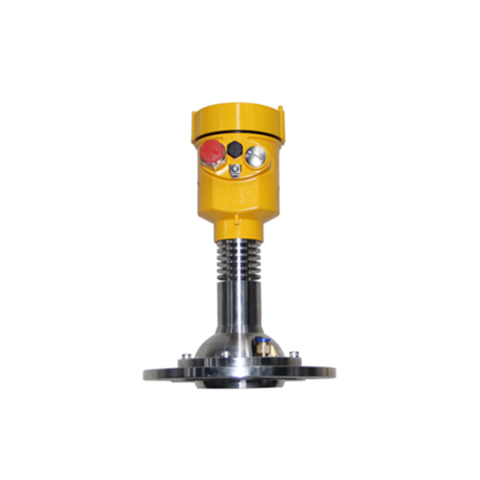
IX. How Should a Radar Level Gauge Be Wired?
Radar level instruments may use different power supply and signal output configurations.
Before wiring, always check:
Instrument nameplate;
Rated supply voltage;
AC or DC power supply;
Terminal definitions;
Signal polarity;
Grounding terminal.
Do not perform wiring solely based on experience with other instrument models.
Some radar level gauge installation documents recommend shielded twisted-pair cable with a conductor cross-sectional area of approximately 0.5 mm²–2 mm².
The actual cable specification should be determined according to:
Instrument power supply;
Signal type;
Cable distance;
On-site electrical standards.
X. Typical Radar Level Gauge Wiring Procedure
On-site wiring typically includes the following steps:
Disconnect the power supply;
Check the instrument nameplate and power supply requirements;
Open the instrument terminal compartment;
Feed the cable into the instrument through the cable gland;
Connect the power and signal wires according to the terminal markings;
Carry out shielding and grounding according to electrical specifications;
Check the wiring and polarity again;
Tighten the cable gland;
Check enclosure sealing;
Restore power after confirming that everything is correct.
The specific wire stripping length, tool specifications, and terminal operating procedures should be carried out according to the manual for the corresponding model.
XI. Why Do Radar Level Gauges Require Shielding and Grounding?
Industrial sites may contain motors, variable-frequency drives, pumps, high-power cables, and other electrical equipment that can generate electromagnetic interference.
Proper use of shielded cables and grounding can help improve signal transmission stability.
Whether the cable shield should use single-point grounding or another grounding method should be determined according to the instrument manual and project electrical design requirements.
Improper multi-point grounding may create ground loops, so a single universal grounding method should not be applied to every installation.
XII. What Is the Purpose of Standards Related to Radar Level Gauges?
Standards related to radar level gauges are mainly used to regulate product design, manufacturing, testing, installation, and industrial applications.
Engineering projects should focus on requirements related to:
Electrical safety;
Explosion protection;
Environmental protection;
Installation;
Signal interfaces;
Project technical specifications.
The purpose of standards is not simply to add content to a product description, but to help confirm whether an instrument meets the technical and safety requirements of the actual project.
XIII. Radar Level Gauge Selection Checklist
| Item | Information to Confirm |
|---|---|
| Medium Type | Liquid, powder, or granular material |
| Medium Name | Coal, cement, grain, chemical raw materials, etc. |
| Measurement Distance | Maximum level measurement distance |
| Dust | Whether large amounts of dust are present |
| Steam | Whether significant water vapor is present |
| Corrosiveness | Whether corrosive liquids or gases are present |
| Crystallization | Whether the medium is prone to crystallization |
| Foam | Whether a large amount of foam is present |
| Fluctuation | Whether the liquid surface fluctuates significantly |
| Viscosity | Whether the medium is prone to adhesion |
| Antenna | Select according to actual site operating conditions |
| Installation Connection | Threaded or flange connection |
| Wiring | Follow the instrument nameplate and terminal diagram |
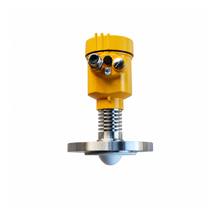
FAQ
Q1: What Is an FMCW Radar Level Gauge?
FMCW radar continuously changes the transmitted frequency and analyzes the frequency difference between the transmitted signal and the reflected signal to calculate distance, which is then converted into liquid level or material level.
Q2: Do All FMCW Radar Level Gauges Use 24 GHz?
No. 24 GHz is only one operating frequency used by certain products. Different radar level gauges may use different operating frequencies and sweep bandwidths. Specific parameters should be confirmed from the corresponding product datasheet.
Q3: Why Should the Steel Cable of a Guided Wave Radar Avoid Contact with the Tank Wall?
Contact between the steel cable and metal structures may generate additional reflections, while long-term friction may also cause mechanical wear. Therefore, reasonable clearance should be maintained during installation.
Q4: Must a Radar Level Gauge Use 0.5–2 mm² Cable?
Not necessarily. This range is specified for certain products. The actual cable specification should be determined according to the specific instrument manual, cable distance, and on-site electrical standards.
Q5: Is Confirming the Measurement Range Alone Enough When Selecting a Radar Level Gauge?
No. The medium, temperature, pressure, dust, steam, corrosion, crystallization, foam, viscosity, installation connection, and other operating conditions should also be confirmed.
Q6: Why Should an Outdoor Radar Level Gauge Cable Have a Drip Loop?
A drip loop reduces the risk of rainwater or condensation traveling along the cable into the instrument cable entry and helps improve the waterproof reliability of outdoor installations.
Conclusion
FMCW radar level instruments measure distance using linear frequency-swept radar signals and can be used for level monitoring of coal, cement, grain, alumina, limestone, chemical raw materials, and other media.
In practical applications, radar level gauge measurement performance depends not only on measurement range but is also closely related to:
Medium characteristics, dust, steam, corrosion, crystallization, foam, antenna type, and installation conditions.
When installing guided wave radar, particular attention should be paid to ensuring that the probe rod or steel cable is positioned properly and does not contact surrounding metal structures.
For electrical installation, particular attention should be paid to:
Power supply, terminals, shielding, grounding, and cable entry sealing.
Specific dimensions, cable specifications, test parameters, and wiring methods should be based on the datasheet, installation manual, and project electrical specifications for the corresponding radar level gauge.
