


 Chinese
 Spanish
 Russian
 Portuguese
 French
 German
 Indonesian
 Thai
Thai Vietnamese
 Arabic
 Italian
 Turkish
 Polish
 Japanese
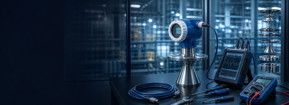
Technical guide by Arvin, METRAVON Instruments · Reviewed September 2026
Short answer
Preserve the fault evidence before changing anything. Troubleshoot in a controlled sequence: process and mechanical conditions, power and wiring, device parameters, control-system scaling, then network and platform behavior. Change one variable at a time and record the result. Replacing hardware, changing parameters and editing PLC logic simultaneously destroys the evidence needed to identify the root cause.
This guide supports safe initial diagnosis. Work involving live electrical circuits, pressure containment, hazardous areas, lifting, confined-space entry or protective interlocks must follow site procedures and be performed by qualified personnel.
Evidence to collect first
- Fault time, process state, filling or discharge activity and recent maintenance or configuration changes.
- Local display, output current, alarm code, echo curve, individual load-cell signals or raw communication frames.
- Product nameplate, complete model, serial or order reference, firmware and operating time.
- Power supply, wiring diagram, loop load, grounding, PLC scaling and approved tag or register list.
- Photographs showing mounting position, process connections, restraints, cables and nearby equipment.
Establish a known reference whenever possible: a measured distance, a known test weight, a simulated 4–20 mA input or one device connected on a short RS485 test link. This separates the field device from downstream system errors.
Symptom-based checks
| Symptom | Check first | Avoid |
|---|---|---|
| Radar value jumps or loses echo | Filling stream, dust, foam, buildup, obstruction, blocking distance and echo curve | Maximizing damping before finding the cause |
| Level switch misses or sticks | Material coverage, adhesion, density, orientation, sensitivity, delay and output logic | Testing only the relay without exposing the probe |
| Weight drifts or will not return to zero | Piping force, restraints, buildup, foundation, temperature and individual sensor outputs | Recalibrating before removing a mechanical force shunt |
| Modbus does not communicate | Physical interface, address, baud rate, parity, function code and termination | Changing several settings at once |
| Modbus value has wrong scale or sign | Register offset, data type, word order, signed format and scaling | Correcting the value with an unexplained software multiplier |
| Platform data is delayed | Device sample, gateway poll, upload interval, network latency and platform processing | Blaming the network without timestamps from each layer |
Radar level troubleshooting
If the value jumps, save the echo profile and note whether filling, agitation, foam or dust changed at the same time. Inspect antenna buildup and the beam path. Confirm the reference point, measuring range, blocking distance, false-echo map and rate-of-change settings before adjusting damping.
If the radar shows a fixed full or empty value, compare the local distance with a known reference and the current output with the PLC value. A fixed nozzle, ladder, wall buildup or vessel bottom echo may have been selected. Also check whether the control system is displaying a configured fault value as a real measurement.
Level switch troubleshooting
When a switch does not trip, confirm that the sensing element is actually covered under the process condition. Check minimum material density, adhesion, probe orientation, mechanical freedom, supply voltage, sensitivity, delay and relay or transistor output. Test both actuation and reset through the complete loop to the PLC and final equipment action.
When a switch remains active after the material falls, inspect buildup, bridging, mechanical binding and excessive sensitivity. Isolate equipment and follow hazardous-area and lockout procedures before cleaning or opening an enclosure.
Weighing-system troubleshooting
For zero drift, inspect piping, flexible connections, mechanical stops, cable trays, debris, foundation movement and temperature effects before recalibration. Compare the raw signal from each load cell. One support with an unusual response can indicate overload, water ingress, wiring damage, binding or poor load sharing.
If the same test weight produces different results at different locations, investigate corner error, platform stiffness and force distribution. For a vessel, inspect each support and every external connection. Confirm units, rated capacity, load-cell sensitivity, excitation, calibration factor and the reliability of the reference load.
4–20 mA and Modbus checks
For a zero or unstable current signal, confirm whether the device is two-wire or four-wire, measure supply voltage under load, check polarity and loop resistance, and place the meter correctly in series. Review configured fault current and whether an isolator or analog input is saturating.
For RS485, use a daisy-chain topology where practical, avoid star branches, confirm polarity, shield grounding, termination, biasing, cable length, duplicate addresses and timeout. Start with one device on a short link. For Modbus, capture the request and response and verify slave address, function code, zero- or one-based register reference, quantity, CRC, data type, word order and scaling.
Gateway and platform checks
Compare timestamps at the instrument, gateway and platform. Distinguish acquisition interval from upload interval and dashboard refresh. During an outage, verify local buffer capacity, clock source, record identity, retransmission and deduplication. A normal online test does not prove store-and-forward operation.
When to stop remote troubleshooting
Stop trial-and-error work and arrange an on-site inspection when there is mechanical damage, pressure leakage, repeated overload, hazardous-area uncertainty, inability to establish a known reference, missing safety documentation or insufficient evidence. Do not bypass a protective interlock or reset safety-related parameters without the approved procedure.
Frequently asked questions
Can the device be reset to factory settings?
Only after backing up range, output, communication and calibration data and defining a recovery plan. A reset can make an otherwise healthy device incompatible with the control system.
Why should only one variable be changed at a time?
It preserves cause and effect. If the symptom disappears after several simultaneous changes, the original fault remains unknown and may return.
Will gateway data be lost during an outage?
That depends on configured storage, overwrite policy, timestamps and the platform's deduplication behavior. Verify the complete chain with a timed disconnect and recovery test.
What should be sent to technical support?
Send the complete model, application conditions, wiring and tag information, recorded symptoms, photographs, parameter backup, raw signals or frames, recent changes and the checks already completed.
Preserve evidence before taking action
Record displayed value, PLC value, alarm state, diagnostics, time and process condition before cycling power or changing parameters. Ask what changed: product, maintenance, wiring, software, power quality or operating rate. Intermittent faults often disappear after a restart, taking the most useful evidence with them. Export logs, echo curves and configuration first when safe.
Classify the symptom as fixed, biased, noisy, intermittent, slow or unavailable. Determine whether it affects one point, one cabinet, one network or the complete site. This scope quickly separates a local sensor issue from shared power, grounding, PLC or communication failure.
Verify the physical process independently
Use a safe independent reference for level, weight, temperature or pressure. Check foam, dust, condensation, buildup, bridging, density change, vibration and flow. A process change can make a valid reading look wrong. Conversely, a plausible value may be stale or frozen, so verify that it changes when the process changes.
Inspect mounting, orientation, blocked nozzles, force shunts, flexible connections and mechanical contact. Compare radar echoes or individual load-cell outputs with the commissioning baseline. Correct physical causes before compensating them in software.
Test power and the signal chain
Measure voltage at the device under load, not only at the supply. Check polarity, terminals, fuses, barriers, grounding, shields and water ingress. For 4–20 mA, measure current and loop voltage, then compare local output, input-card raw count and scaled PLC value. Identify where the first disagreement appears.
For switches, confirm output state at the device and receiving input. For load cells, compare excitation and millivolt output of each channel. Intermittent cable faults may appear only with vibration, temperature or movement; manipulate cables only under an approved safe procedure.
Configuration and application diagnostics
Compare current settings with the approved backup. Check range, units, damping, fault mode, density, geometry and alarm delays. Do not restore factory defaults until the existing configuration is saved and the consequences are understood. A parameter change should test one hypothesis at a time.
For radar, examine wanted and false echoes across the range. For weighing, check zero, load sharing and mechanical freedom. For batch systems, review weight trend, feeder timing and material in flight. A device replacement will not solve an unsuitable installation or control sequence.
Network and data-platform checks
Verify address, baud rate, parity, termination, register mapping, byte order, timestamp and quality. Distinguish communication timeout from a valid zero. Check whether a gateway is serving cached data and whether the platform marks it stale. Use error counters and packet or protocol diagnostics rather than repeated reconnection attempts.
Test one known value end to end. If the field device and PLC agree but the dashboard does not, focus downstream. Confirm clock synchronization when event order appears impossible. After recovery, verify buffered data, duplicates and current-value priority.
Controlled correction and verification
Change one item, repeat the original failure condition and compare objective results. Document root cause, as-found data, action and post-work test. Remove software forces and temporary bypasses, restore covers and update backups. If the cause remains uncertain, state that clearly and define monitoring rather than declaring success after a short stable period.
Use recurring failures to improve design: relocate the sensor, improve sealing, separate cables, add diagnostics or revise maintenance. Track mean time between failures and common causes by equipment family. Troubleshooting creates value when its evidence prevents repetition.
Escalation information
When requesting support, provide model, serial number, firmware, process, installation photographs, wiring, power measurements, configuration, diagnostics, raw and displayed values, timestamps and actions already taken. Describe the expected behaviour and safety impact. Complete evidence avoids repeating basic checks and allows faster, safer recommendations.
Engineering note: Remote advice cannot replace site safety judgment. Follow the approved electrical, pressure, confined-space, lifting and hazardous-area procedures.
Continue your project research: Review our industrial instrumentation troubleshooting resources. For a model-specific recommendation, send your medium, range, process and installation details to METRAVON.
