


 Chinese
 Spanish
 Russian
 Portuguese
 French
 German
 Indonesian
 Thai
 Vietnamese
 Arabic
 Italian
 Turkish
 Polish
 Japanese


Modbus radar integration is complete when the PLC uses the right measurement with the right validity state, not when a communications icon turns green. A successful reply can still contain a distance interpreted as level, a number decoded in the wrong format or a stale value used after polling stops.
Order the Serial Electronics, Not Just a Radar With a Familiar Housing
The METRAVON MV-RD12 has a two-wire 4-20 mA/HART option and a corresponding separately powered RS485 configuration. These are different electrical arrangements. Specify Modbus RTU and obtain the terminal drawing, supply requirement and register document for the actual offered electronics before assigning PLC channels.
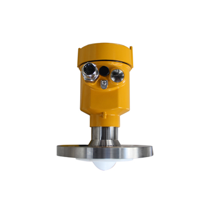
A register map from another radar model is not an acceptable substitute. Ask which values and diagnostics are exposed, whether they are read-only, and which firmware the document covers. If the project requires a quality flag that the proposed unit cannot supply, decide how the receiver will detect invalid measurement before procurement.
Modbus Radar Integration: Build a Tag Sheet Before Programming
| Field | Record | Check |
|---|---|---|
| Address | Device address and the documented register reference. | Distinguish the manual's notation from the offset expected by the PLC driver. |
| Function | The supported read function and permitted register group. | Do not treat an exception response as a slow or missing reply. |
| Format | Integer or floating-point type and multi-register order. | Decode captured raw words before applying engineering scaling. |
| Meaning | Distance, level, unit and any documented multiplier. | Check that the trend changes in the expected direction. |
| Validity | Available status information and the receiver's timeout rule. | Show missing or invalid data separately from a valid unchanging level. |
Read the documented register group rather than probing arbitrary addresses. A Modbus register contains 16 bits, but a process value may occupy several registers. The application map must define their interpretation. Selecting a byte-swap option because it produces a plausible number at one point is not a reliable commissioning method.
Prove the Bus Separately From the Engineering Value
Match baud rate, parity and the other serial settings. Give each connected device a unique address. Start with one instrument and a known connection, then introduce the field cable and additional devices in controlled steps. Check terminal definitions rather than assuming that every manufacturer's A/B labels use the same convention.
Use the designed RS485 trunk, termination and signal reference arrangement. Do not add resistors to every instrument or alter bonding by trial and error. Save request and reply diagnostics when the problem appears only after another device is connected; that evidence is more useful than repeatedly extending the timeout.
Once exchanges are reliable, compare the decoded tag with the instrument's indicated variable at several known process positions. Record the raw words, unit and scaling alongside the result. Keep the radar's geometry setup separate from the PLC conversion so a level offset is not hidden by changing both systems.
Test What Happens When the Value Stops Updating
Under an approved test procedure, interrupt the relevant communications path and verify the PLC timeout, display indication and control response. Restore the link and check that a fresh valid reading is required before normal use resumes. A last-good value can be retained for reference, but its age and invalid state must remain visible.
Confirm the polling schedule for the complete bus, including devices that fail to answer. Excessive retries on one failed instrument can delay the others. Define the acceptable age of a control input from the process requirement, not only from whether the serial port reports errors.
Questions From PLC Integration
Q1. Does RS485 guarantee Modbus RTU compatibility?
No. RS485 describes an electrical interface. The instrument and PLC also need matching protocol support, serial settings and an understood application map. Confirm those details in the supplied configuration rather than relying on the connector label.
Q2. Should a holding-register reference be entered literally into every PLC?
No. Driver addressing conventions differ. Use the driver's documentation together with the instrument map and preserve a working request example in the handover record. Do not publish one universal address adjustment for every controller.
Q3. Why can the value look correct at one level and fail at another?
A wrong format, multiplier or range conversion can occasionally produce a credible result. Compare multiple positions and the raw register values. Check signedness and multi-register interpretation before concluding that the radar measurement is nonlinear.
Summary
Specify the electronics, document each tag and prove both data meaning and failure handling. Request an MV-RD12 serial-interface review with the PLC type and required variables. Include the register-document and commissioning requirements in the order so integration does not depend on guessed settings.
