


 Chinese
 Spanish
 Russian
 Portuguese
 French
 German
 Indonesian
 Thai
 Vietnamese
 Arabic
 Italian
 Turkish
 Polish
 Japanese



METRAVON MV-RD909 is a long-range radar water level meter with a listed maximum measuring distance of 70 m. It uses 26 GHz pulses to measure the gap between the radar reference and the water surface. That range is relevant to elevated bridges and other high mounting positions; it is not a measurement of the river's underwater depth.
Establish the required distance at low water
Start with the mounting elevation and the lowest surface that the station must report. Then check the highest water level against the antenna's near-range exclusion. A site may fit the maximum distance but fail the high-water clearance requirement, so both ends belong on the section drawing.
At longer distances, assess the full region illuminated by the selected antenna. Bridge members, banks or exposed features can compete with the useful water return. Request the actual antenna dimensions and beam information with the quotation instead of assuming every MV-RD909 uses one beam angle.
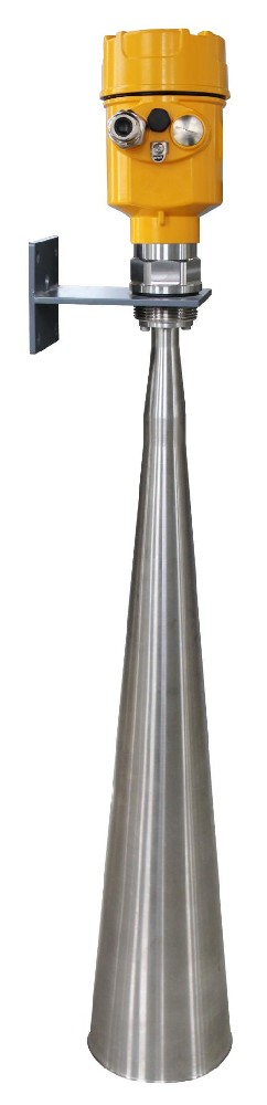
Parameters to carry into the station design
| Parameter | MV-RD909 selection |
|---|---|
| Maximum listed distance | 70 m |
| Frequency | 26 GHz |
| Process duty | Atmospheric water-level monitoring |
| Connection choices | Thread, bracket or specified flange |
| Housing | Confirm the metal or plastic enclosure and its selected IP rating. |
| Output and power | Specify 24 VDC two-wire 4-20 mA/HART or the separately powered RS485/Modbus version. |
| Performance acceptance | Obtain the ordered version's accuracy, usable range and environmental limits in writing. |
Do not combine the longest range, a temperature limit and a general accuracy figure from different configurations. For a demanding site, ask which performance specification applies to the supplied antenna and electronics and how it will be checked at the required distance.
Mounting stability affects the water-elevation record
Use a support that retains alignment and can be inspected without disturbing the reference unnecessarily. Survey the instrument datum after installation. If the bracket moves during servicing or structural work, check that reference again before interpreting a step change as a real water-level event.
A nominally downward-looking installation can still receive reflections from surrounding steelwork. Document nearby members and the water surface under the beam through the operating interval. Configure any false-echo handling using the applicable procedure and a known process state, not as a substitute for a clear mounting position.
Make the complete data path part of acceptance
The instrument measures locally; a logger or RTU acquires and transmits the result. Assign the conversion from measured distance to water elevation to a defined part of that chain. Applying the same offset at both the sensor and host can create an error even when each connection works.
Verify the required variables, units, timestamps and invalid-data handling at the destination. A recent communication timestamp should not be mistaken for a fresh measurement if a device has retained its previous reading. Test link loss and recovery as well as normal acquisition.
For exposed installations, review the power, signal routes and bonding with the responsible electrical designer. The radar surge-protection guide describes the circuit information needed for that review; it is not a substitute for the site's protection design.
Long-range application questions
Q1. Does 70 m mean the station can measure 70 m of water depth?
No. It describes the radar-to-surface distance. Water depth below the surface requires a bed reference or another measurement. Keep the required variable explicit when selecting the sensor and configuring the logger.
Q2. Can a successful high-water test prove low-water performance?
It only establishes the tested condition. At low water the useful return travels farther and the surrounding scene may change. Where full-interval testing is not possible initially, document the untested conditions and plan a later check rather than claiming complete coverage.
Q3. Will a longer-range model solve every weak reading?
Not if the cause is an obstruction, poor alignment or an incorrect reference. Identify the cause first. A replacement must resolve a specific limitation and still fit the mounting and electrical arrangement.
Q4. Is a 70 m model necessary for a shorter site?
Compare the required interval with a suitable shorter-range instrument such as MV-RD908S. Maximum distance alone does not determine accuracy, ingress protection or suitability for the surrounding structures.
Prepare a site-based quotation request
Include mounting elevation, water-level extremes, a section drawing and photographs of the measurement path in your MV-RD909 request. Add the power system, receiving equipment and required performance evidence. Identify who will survey the datum and verify the low-water condition so those tasks are not omitted from the project scope.
