


 Chinese
 Spanish
 Russian
 Portuguese
 French
 German
 Indonesian
 Thai
 Vietnamese
 Arabic
 Italian
 Turkish
 Polish
 Japanese


A Curiotec load cell replacement enquiry should identify the installed sensor and the indicator that will remain in service. Matching capacity and fitting the bolt holes does not establish that the new bridge can operate correctly with the existing electronics. Treat the brand name as a way to identify the old equipment, not as a cross-reference specification.
Start at the indicator terminals
Obtain the indicator manual, terminal assignments, excitation voltage, permitted bridge resistance and millivolt input range. Photograph the existing junction-box connections before approved disconnection. Trace excitation, signal, sense and shield functions individually; cable colours from one manufacturer must not be transferred to another.
For several parallel cells, the indicator supplies the combined bridge load. Equal bridge input resistances R connected in parallel give an equivalent resistance of R divided by the cell count. Use the actual input resistance, not the output resistance or cable resistance. A replacement with different bridge resistance can change the required excitation current.
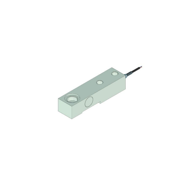
Curiotec load cell replacement: compare the signal, not just the label
The METRAVON MV-LC0050 is a cantilever-beam model with nominal 2 mV/V sensitivity and specified 10-12 V DC excitation. At 10 V excitation, its nominal full-scale signal is 20 mV. This is a compatibility calculation, not a calibration result for a delivered sensor. The indicator also needs enough input headroom for dead load and the intended operating span.
| Check | Evidence for retaining the indicator |
|---|---|
| Excitation | The actual supply lies within the replacement's allowed range under the complete bridge load. |
| Input | The receiver accepts the expected signal and polarity without saturating at maximum applied load. |
| Cable | Sense wiring, shield termination and cable extensions follow the applicable instrument instructions. |
| Adjustment | Zero, span and any multi-cell balancing remain achievable after installation. |
Keep mechanical approval separate
An electrical match cannot correct an unsuitable loading point. Compare the approved capacity-specific drawing with the mounting base, fasteners, load-introduction hardware and clearance for measuring deflection. Do not approve MV-LC0050 solely because the old sensor is described as a beam. Mixing cells within one scale also needs a review of their load sharing and electrical response.
After installation, compare unloaded and known-load readings at the relevant positions, then unload and check the return to zero. Record the new sensor identity and indicator settings. A successful zero adjustment alone does not demonstrate span or corner performance.
Replacement questions
Q1. The indicator displays weight. Does that prove compatibility?
It proves only that a signal is being interpreted. Incorrect sensitivity, polarity or excitation can still produce plausible numbers. Compare readings against independently known loads before returning the scale to use.
Q2. What if the original model number is unreadable?
Send photographs, dimensions, wiring records and the indicator identification. Any proposal remains conditional until the missing load-path and electrical details are established; a brand name cannot fill those gaps.
Summary
Retaining an indicator can reduce retrofit work only when its bridge supply and input suit the proposed sensor. Submit the old sensor details, indicator manual and mounting drawing for a documented replacement review.
