


 Chinese
 Spanish
 Russian
 Portuguese
 French
 German
 Indonesian
 Thai
 Vietnamese
 Arabic
 Italian
 Turkish
 Polish
 Japanese


A silo weighing system measures the load carried by the vessel supports. It can provide mass inventory without converting a material surface into tonnes, but it also responds to forces from connected pipes, restraints and auxiliary equipment. For a METRAVON installation, the first purchasing decision is therefore whether the structure can transfer its load through the proposed modules consistently, not which display has the most digits.
Silo weighing starts with the support reactions
Prepare a load schedule for the vessel, its maximum contents and every item carried by the weighing structure. Include insulation, filters, mixers and access equipment where their weight is transmitted through the supports. A net-weight display subtracts tare numerically; it does not remove the empty vessel's load from a sensor.
The average gross load per support is only a starting point. An offset centre of gravity, uneven filling or unequal foundation stiffness can put a larger reaction on one support. The structural assessment must also address relevant wind, uplift, lateral and maintenance loads. Have the responsible engineer establish those reactions and the restraint arrangement before selecting capacities.
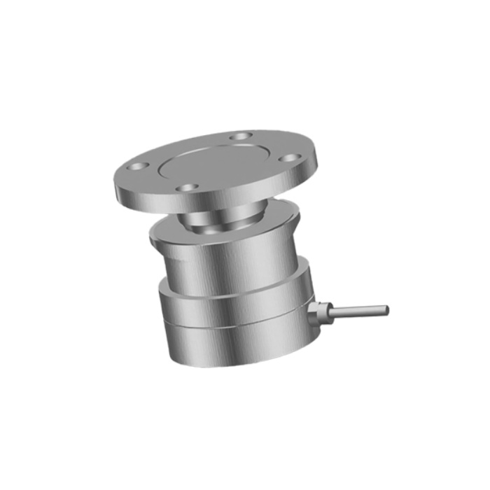
The MV-WM0007 provides a round-flange compression arrangement for assessing suitable vessel installations. Do not infer uplift capacity, permitted side load or thermal movement from the photograph. Obtain the drawing and load limits for the proposed assembly. A different module geometry may be needed where the existing support cannot accommodate that arrangement.
A large capacity margin may protect against a particular overload while reducing the useful signal change from a small quantity of material. Define the smallest stock change that operations needs to recognise and the permitted error at that load. The instrument and sensor combination should be evaluated against that requirement, separately from the structural capacity check.
Find the forces that bypass the sensors
| Connection | What to inspect before calibration |
|---|---|
| Product pipes | Observe how inlet and outlet connections move with temperature, pressure and vessel displacement. A flexible section can still exert force. |
| Dust extraction | Check whether ducts or filter supports carry part of the vessel load or pull on the roof when the fan operates. |
| Access structures | Identify ladders, platforms and handrails connected to both the vessel and an independent structure. |
| Restraints | Verify the designed clearances and load direction. Protection against movement must not become an unintended vertical support. |
| Services | Inspect conduit, cable bundles and bonding connections for mechanical restraint while retaining required electrical protection. |
| Foundation | Check seating, stiffness and settlement at each support, rather than correcting unequal reactions only through electrical adjustment. |
Compare the empty-vessel reading with connected equipment in its normal operating states. A weight change when a valve moves or a fan starts, without material entering the silo, is useful evidence of an external force. Record that response before changing zero or filtering. Otherwise, an adjustment can hide the cause at one condition and leave it active at another.
Retrofitting modules also changes the support arrangement. Installation height affects pipe alignment, discharge clearance and access for later sensor replacement. Temporary support, lifting and structural modifications require an engineered work method; they are not part of routine instrument calibration. Confirm who owns that work and whether the silo must be emptied or taken out of service.
Specify the measurement chain as well as the modules
The sensor output, excitation requirement and combined electrical load must be compatible with the receiving instrument. For an analogue multi-support system, identify the junction box, cable lengths, shield termination and access to individual sensor signals. A total weight that looks reasonable does not prove that each support is carrying the intended load.
The MV-WI0009 weighing controller can be assessed where local weight indication and discrete control signals are needed. Its published capabilities include four relay outputs and four isolated inputs. Modbus RTU and 4-20 mA must be specified as options. The controller does not make the complete silo a certified weighing system or supply an approved restraint design.
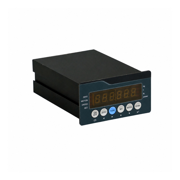
For a PLC connection, agree the engineering unit, gross or net value, sign, scaling and update behaviour. Define what the receiving system does with an overload, unstable value or communication timeout. A last-known reading may be useful for diagnosis, but it must not remain indistinguishable from a current valid weight.
Agree an installed-system acceptance test
Separate mechanical checks, calibration and process verification. Mechanical checks establish that the intended load reaches the sensors. Calibration relates the measured signal to known mass. Process verification tests whether the installed arrangement remains useful during the conditions in which the customer will rely on it.
Use an agreed reference method that exercises the vessel and its supports. Test weights may be practical for part of the range; a controlled material transfer may cover other operating points. The reference uncertainty, retained material and transfer losses must be addressed. An electrical simulator checks the signal chain but cannot show whether a pipe is supporting part of the silo.
Record increasing and decreasing loads, repeat measurements and return to the same empty or known-tare state. Include the operating state of valves, agitators and connected ducts. Where access permits, compare individual support responses. Set acceptance limits in mass units and at specified loads so a percentage of full capacity is not confused with a percentage of a small net inventory.
Keep the as-found values when investigating drift. Re-zeroing after every delivery can erase evidence of material buildup, mechanical binding or a changing pipe force. After a structural repair or pipe modification, repeat the affected checks before relying on the previous calibration.
Questions before a silo retrofit
Q1. Can modules be added without changing the existing pipes?
That depends on the connections and required measurement performance. Review the force transmitted by each line over temperature and operating movement. If a connection cannot be modified, quantify its effect and decide whether the resulting uncertainty is acceptable. Do not promise an accurate retrofit before this review.
Q2. Should all support readings be identical?
Not necessarily. Real load distribution can be unequal, and raw outputs depend on sensor capacity, sensitivity and excitation. Compare the measured reactions with the design and calibration information. Trimming every signal to the same number can conceal a structural problem.
Q3. Does a more precise load cell solve a drifting empty reading?
Only if the sensor is the limiting cause. First investigate changing external forces, contact at stops, moisture in connections and support movement. Replacing sensors without identifying the mechanism may leave the drift unchanged.
Q4. What needs to be included in a quotation request?
Provide the support drawing, empty and maximum gross loads, calculated support reactions, installation height and connected services. Add the required mass resolution, permissible error, controller interface and feasible calibration method. Separate the supply of instruments from lifting, fabrication, structural approval and site commissioning.
Summary
Choose silo weighing when mass is the required result and the support structure can be made suitable for measurement. Resolve external forces and acceptance conditions before selecting a module and instrument. Send the vessel drawings and weighing requirements to METRAVON for a configuration review; for a comparison with level-derived stock, see silo inventory monitoring.
